

46 Bearing Fault Diagnosis Using Grad-CAM …
529
46.2.2 Step 2: Characteristic Frequency Magnitude
Extraction
Bearing failures generate periodic burst signals which are represented as bearing
characteristic frequency in the spectrum. The bearing characteristic frequency is
categorized to ball pass frequency on outer race, BPFO, ball pass frequency on inner
race, BPFI, and ball spin frequency, BSF. Outer race failure, Inner race failure, and
Rolling element failure of the bearing cause BPFO, BPFI, and 2 × BSF, respectively.
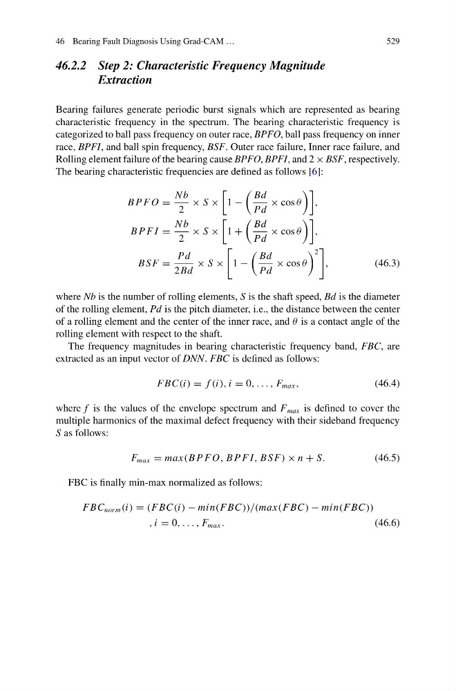
The bearing characteristic frequencies are defined as follows [6]:
B P F O =
N b
2
× S ×
1 −
Bd
Pd
× cos θ
,
B P F I =
N b
2
× S ×
1 +
Bd
Pd
× cos θ
,
B S F =
Pd
2Bd
× S ×
1 −
Bd
Pd
× cos θ
2
,
(46.3)
where Nb is the number of rolling elements, S is the shaft speed, Bd is the diameter
of the rolling element, Pd is the pitch diameter, i.e., the distance between the center
of a rolling element and the center of the inner race, and θ is a contact angle of the
rolling element with respect to the shaft.
The frequency magnitudes in bearing characteristic frequency band, FBC, are
extracted as an input vector of DNN. FBC is defined as follows:
F BC(i) = f (i), i = 0, . . . , F max ,
(46.4)
where f is the values of the envelope spectrum and F max is defined to cover the
multiple harmonics of the maximal defect frequency with their sideband frequency
S as follows:
F max = max(B P F O, B P F I, B S F) × n + S.
(46.5)
FBC is finally min-max normalized as follows:
F BC norm (i) = (F BC(i) − min(F BC))/(max(F BC) − min(F BC))
, i = 0, . . . , F max .
(46.6)
529
46.2.2 Step 2: Characteristic Frequency Magnitude
Extraction
Bearing failures generate periodic burst signals which are represented as bearing
characteristic frequency in the spectrum. The bearing characteristic frequency is
categorized to ball pass frequency on outer race, BPFO, ball pass frequency on inner
race, BPFI, and ball spin frequency, BSF. Outer race failure, Inner race failure, and
Rolling element failure of the bearing cause BPFO, BPFI, and 2 × BSF, respectively.
The bearing characteristic frequencies are defined as follows [6]:
B P F O =
N b
2
× S ×
1 −
Bd
Pd
× cos θ
,
B P F I =
N b
2
× S ×
1 +
Bd
Pd
× cos θ
,
B S F =
Pd
2Bd
× S ×
1 −
Bd
Pd
× cos θ
2
,
(46.3)
where Nb is the number of rolling elements, S is the shaft speed, Bd is the diameter
of the rolling element, Pd is the pitch diameter, i.e., the distance between the center
of a rolling element and the center of the inner race, and θ is a contact angle of the
rolling element with respect to the shaft.
The frequency magnitudes in bearing characteristic frequency band, FBC, are
extracted as an input vector of DNN. FBC is defined as follows:
F BC(i) = f (i), i = 0, . . . , F max ,
(46.4)
where f is the values of the envelope spectrum and F max is defined to cover the
multiple harmonics of the maximal defect frequency with their sideband frequency
S as follows:
F max = max(B P F O, B P F I, B S F) × n + S.
(46.5)
FBC is finally min-max normalized as follows:
F BC norm (i) = (F BC(i) − min(F BC))/(max(F BC) − min(F BC))
, i = 0, . . . , F max .
(46.6)