

506
Z. Wu et al.
bottom chord, and the distance between sensors is also not more than 4.5 m, the
simulated AE sources on the web rods can only be located at the welding point of
the web rod with the main chord. The AE sources location error is large and can’t
reflect the real positioning. This is mainly because using the TDOA algorithm for
the linear positioning. The arrival time difference between the simulated acoustic
emission sources on the web rod to a group of adjacent sensors is the same as
that of its welding point of web rod and main chord. And the AE source location
calculated according to TDOA is the same. Therefore, for the large truss beam, the
linear positioning method can’t correctly locate the AE sources in the web rod.
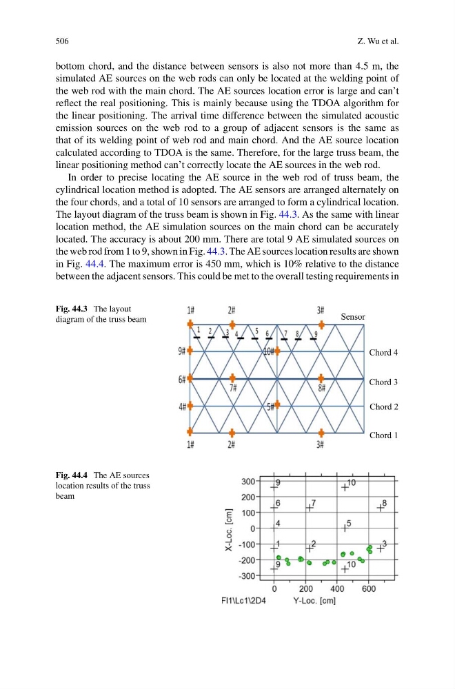
In order to precise locating the AE source in the web rod of truss beam, the
cylindrical location method is adopted. The AE sensors are arranged alternately on
the four chords, and a total of 10 sensors are arranged to form a cylindrical location.
The layout diagram of the truss beam is shown in Fig. 44.3. As the same with linear
location method, the AE simulation sources on the main chord can be accurately
located. The accuracy is about 200 mm. There are total 9 AE simulated sources on
the web rod from 1 to 9, shown in Fig. 44.3. The AE sources location results are shown
in Fig. 44.4. The maximum error is 450 mm, which is 10% relative to the distance
between the adjacent sensors. This could be met to the overall testing requirements in
Fig. 44.3 The layout
diagram of the truss beam
Chord 1
Chord 2
Chord 3
Chord 4
Sensor
Fig. 44.4 The AE sources
location results of the truss
beam
Z. Wu et al.
bottom chord, and the distance between sensors is also not more than 4.5 m, the
simulated AE sources on the web rods can only be located at the welding point of
the web rod with the main chord. The AE sources location error is large and can’t
reflect the real positioning. This is mainly because using the TDOA algorithm for
the linear positioning. The arrival time difference between the simulated acoustic
emission sources on the web rod to a group of adjacent sensors is the same as
that of its welding point of web rod and main chord. And the AE source location
calculated according to TDOA is the same. Therefore, for the large truss beam, the
linear positioning method can’t correctly locate the AE sources in the web rod.
In order to precise locating the AE source in the web rod of truss beam, the
cylindrical location method is adopted. The AE sensors are arranged alternately on
the four chords, and a total of 10 sensors are arranged to form a cylindrical location.
The layout diagram of the truss beam is shown in Fig. 44.3. As the same with linear
location method, the AE simulation sources on the main chord can be accurately
located. The accuracy is about 200 mm. There are total 9 AE simulated sources on
the web rod from 1 to 9, shown in Fig. 44.3. The AE sources location results are shown
in Fig. 44.4. The maximum error is 450 mm, which is 10% relative to the distance
between the adjacent sensors. This could be met to the overall testing requirements in
Fig. 44.3 The layout
diagram of the truss beam
Chord 1
Chord 2
Chord 3
Chord 4
Sensor
Fig. 44.4 The AE sources
location results of the truss
beam