

42 Damage Localization of Debris Cloud Hypervelocity Impact …
477
42.2 HVI Experiment
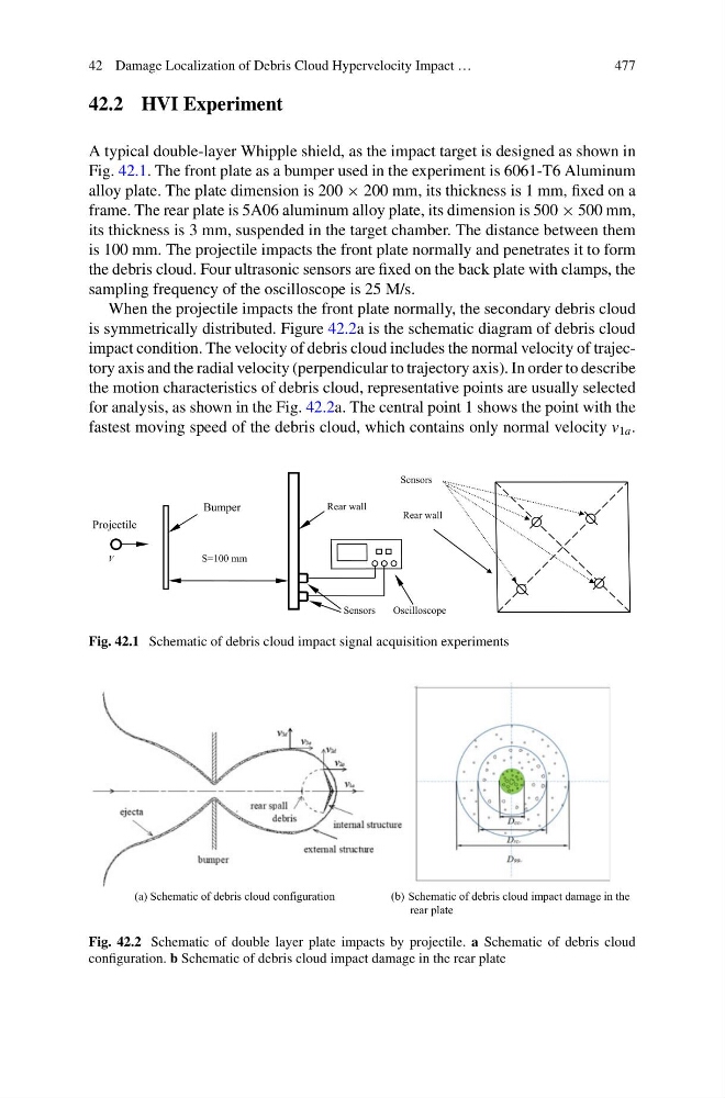
A typical double-layer Whipple shield, as the impact target is designed as shown in
Fig. 42.1. The front plate as a bumper used in the experiment is 6061-T6 Aluminum
alloy plate. The plate dimension is 200 × 200 mm, its thickness is 1 mm, fixed on a
frame. The rear plate is 5A06 aluminum alloy plate, its dimension is 500 × 500 mm,
its thickness is 3 mm, suspended in the target chamber. The distance between them
is 100 mm. The projectile impacts the front plate normally and penetrates it to form
the debris cloud. Four ultrasonic sensors are fixed on the back plate with clamps, the
sampling frequency of the oscilloscope is 25 M/s.
When the projectile impacts the front plate normally, the secondary debris cloud
is symmetrically distributed. Figure 42.2a is the schematic diagram of debris cloud
impact condition. The velocity of debris cloud includes the normal velocity of trajectory axis and the radial velocity (perpendicular to trajectory axis). In order to describe
the motion characteristics of debris cloud, representative points are usually selected
for analysis, as shown in the Fig. 42.2a. The central point 1 shows the point with the
fastest moving speed of the debris cloud, which contains only normal velocity v 1a .
Sensors
V
Projectile
Bumper
S=100 mm
Rear wall
Sensors
Oscilloscope
Rear wall
Fig. 42.1 Schematic of debris cloud impact signal acquisition experiments
(a) Schematic of debris cloud configuration
(b) Schematic of debris cloud impact damage in the
rear plate
Fig. 42.2 Schematic of double layer plate impacts by projectile. a Schematic of debris cloud
configuration. b Schematic of debris cloud impact damage in the rear plate
477
42.2 HVI Experiment
A typical double-layer Whipple shield, as the impact target is designed as shown in
Fig. 42.1. The front plate as a bumper used in the experiment is 6061-T6 Aluminum
alloy plate. The plate dimension is 200 × 200 mm, its thickness is 1 mm, fixed on a
frame. The rear plate is 5A06 aluminum alloy plate, its dimension is 500 × 500 mm,
its thickness is 3 mm, suspended in the target chamber. The distance between them
is 100 mm. The projectile impacts the front plate normally and penetrates it to form
the debris cloud. Four ultrasonic sensors are fixed on the back plate with clamps, the
sampling frequency of the oscilloscope is 25 M/s.
When the projectile impacts the front plate normally, the secondary debris cloud
is symmetrically distributed. Figure 42.2a is the schematic diagram of debris cloud
impact condition. The velocity of debris cloud includes the normal velocity of trajectory axis and the radial velocity (perpendicular to trajectory axis). In order to describe
the motion characteristics of debris cloud, representative points are usually selected
for analysis, as shown in the Fig. 42.2a. The central point 1 shows the point with the
fastest moving speed of the debris cloud, which contains only normal velocity v 1a .
Sensors
V
Projectile
Bumper
S=100 mm
Rear wall
Sensors
Oscilloscope
Rear wall
Fig. 42.1 Schematic of debris cloud impact signal acquisition experiments
(a) Schematic of debris cloud configuration
(b) Schematic of debris cloud impact damage in the
rear plate
Fig. 42.2 Schematic of double layer plate impacts by projectile. a Schematic of debris cloud
configuration. b Schematic of debris cloud impact damage in the rear plate