

442
X. Li et al.
In this paper, the AE signal is collected through the AE instrument during the
axial compression failure test of the composite barrel. By analyzing the AE signal
such as energy, AE hits, amplitude, and duration, it is concluded that the AE signal
can accurately reflect the load change and damage of the test piece. By analyzing the
signal frequency, the correspondence between the damage type of the test piece and
the signal frequency is obtained.
39.2 Test Method
39.2.1 Test Products
The test product is a composite cylindrical part. The total height of the test part is
700 mm and the diameter is 1000 mm. An axial compression failure test is required
for the test product. During the test, the test piece is placed vertically and fixed on
the test bench, and a 200 T material testing machine is used to apply the axial load
to the test piece.
39.2.2 AE Instrument and Probe Arrangement
The AE loading test was performed at the same distance from the upper surface to the
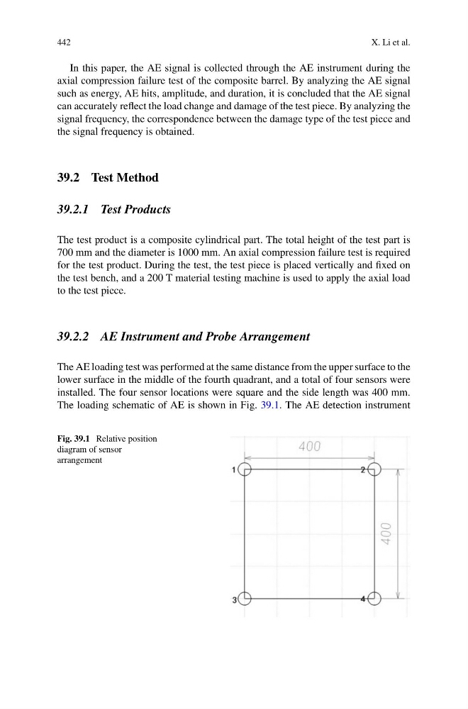
lower surface in the middle of the fourth quadrant, and a total of four sensors were
installed. The four sensor locations were square and the side length was 400 mm.
The loading schematic of AE is shown in Fig. 39.1. The AE detection instrument
Fig. 39.1 Relative position
diagram of sensor
arrangement
X. Li et al.
In this paper, the AE signal is collected through the AE instrument during the
axial compression failure test of the composite barrel. By analyzing the AE signal
such as energy, AE hits, amplitude, and duration, it is concluded that the AE signal
can accurately reflect the load change and damage of the test piece. By analyzing the
signal frequency, the correspondence between the damage type of the test piece and
the signal frequency is obtained.
39.2 Test Method
39.2.1 Test Products
The test product is a composite cylindrical part. The total height of the test part is
700 mm and the diameter is 1000 mm. An axial compression failure test is required
for the test product. During the test, the test piece is placed vertically and fixed on
the test bench, and a 200 T material testing machine is used to apply the axial load
to the test piece.
39.2.2 AE Instrument and Probe Arrangement
The AE loading test was performed at the same distance from the upper surface to the
lower surface in the middle of the fourth quadrant, and a total of four sensors were
installed. The four sensor locations were square and the side length was 400 mm.
The loading schematic of AE is shown in Fig. 39.1. The AE detection instrument
Fig. 39.1 Relative position
diagram of sensor
arrangement