

328
H. Asaue et al.
velocity in each element corresponding to the observed propagation time of multiple
waves over the structure, resulting in forming the tomogram of the elastic wave
velocity over the target area [5]. Through these steps, velocity distributions were
determined in the structure.
27.3 Measurement Condition
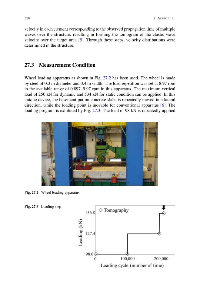
Wheel loading apparatus as shown in Fig. 27.2 has been used. The wheel is made
by steel of 0.3 m diameter and 0.4 m width. The load repetition was set at 8.97 rpm
in the available range of 0.897–9.97 rpm in this apparatus. The maximum vertical
load of 250 kN for dynamic and 534 kN for static condition can be applied. In this
unique device, the basement put on concrete slabs is repeatedly moved in a lateral
direction, while the loading point is movable for conventional apparatus [6]. The
loading program is exhibited by Fig. 27.3. The load of 98 kN is repeatedly applied
Fig. 27.2 Wheel loading apparatus
Fig. 27.3 Loading step
H. Asaue et al.
velocity in each element corresponding to the observed propagation time of multiple
waves over the structure, resulting in forming the tomogram of the elastic wave
velocity over the target area [5]. Through these steps, velocity distributions were
determined in the structure.
27.3 Measurement Condition
Wheel loading apparatus as shown in Fig. 27.2 has been used. The wheel is made
by steel of 0.3 m diameter and 0.4 m width. The load repetition was set at 8.97 rpm
in the available range of 0.897–9.97 rpm in this apparatus. The maximum vertical
load of 250 kN for dynamic and 534 kN for static condition can be applied. In this
unique device, the basement put on concrete slabs is repeatedly moved in a lateral
direction, while the loading point is movable for conventional apparatus [6]. The
loading program is exhibited by Fig. 27.3. The load of 98 kN is repeatedly applied
Fig. 27.2 Wheel loading apparatus
Fig. 27.3 Loading step