

20 Experiment Research on Tensile Process of Glass…
225
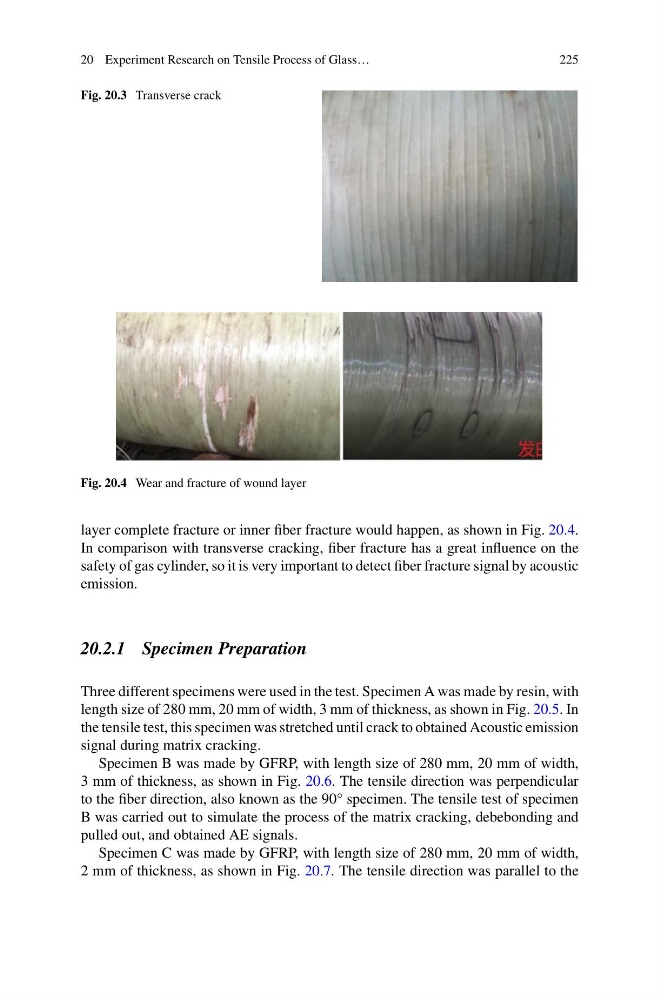
Fig. 20.3 Transverse crack
Fig. 20.4 Wear and fracture of wound layer
layer complete fracture or inner fiber fracture would happen, as shown in Fig. 20.4.
In comparison with transverse cracking, fiber fracture has a great influence on the
safety of gas cylinder, so it is very important to detect fiber fracture signal by acoustic
emission.
20.2.1 Specimen Preparation
Three different specimens were used in the test. Specimen A was made by resin, with
length size of 280 mm, 20 mm of width, 3 mm of thickness, as shown in Fig. 20.5. In
the tensile test, this specimen was stretched until crack to obtained Acoustic emission
signal during matrix cracking.
Specimen B was made by GFRP, with length size of 280 mm, 20 mm of width,
3 mm of thickness, as shown in Fig. 20.6. The tensile direction was perpendicular
to the fiber direction, also known as the 90° specimen. The tensile test of specimen
B was carried out to simulate the process of the matrix cracking, debebonding and
pulled out, and obtained AE signals.
Specimen C was made by GFRP, with length size of 280 mm, 20 mm of width,
2 mm of thickness, as shown in Fig. 20.7. The tensile direction was parallel to the
225
Fig. 20.3 Transverse crack
Fig. 20.4 Wear and fracture of wound layer
layer complete fracture or inner fiber fracture would happen, as shown in Fig. 20.4.
In comparison with transverse cracking, fiber fracture has a great influence on the
safety of gas cylinder, so it is very important to detect fiber fracture signal by acoustic
emission.
20.2.1 Specimen Preparation
Three different specimens were used in the test. Specimen A was made by resin, with
length size of 280 mm, 20 mm of width, 3 mm of thickness, as shown in Fig. 20.5. In
the tensile test, this specimen was stretched until crack to obtained Acoustic emission
signal during matrix cracking.
Specimen B was made by GFRP, with length size of 280 mm, 20 mm of width,
3 mm of thickness, as shown in Fig. 20.6. The tensile direction was perpendicular
to the fiber direction, also known as the 90° specimen. The tensile test of specimen
B was carried out to simulate the process of the matrix cracking, debebonding and
pulled out, and obtained AE signals.
Specimen C was made by GFRP, with length size of 280 mm, 20 mm of width,
2 mm of thickness, as shown in Fig. 20.7. The tensile direction was parallel to the