

9 Burst Analysis for Multi-Level Leakage Detection in Water-Filled Pipeline …
95
techniques using the ECFAR algorithm. The method is evaluated by the performance
of the classification of multi-level leakage and the result is presented in Sect. 9.4. In
the end, Sect. 9.5 provides conclusions and issues for future implementation.
9.2 Seed to Data Acquisition System and the Experimental
Testbed Setup
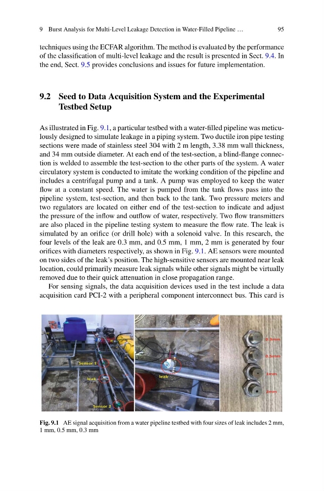
As illustrated in Fig. 9.1, a particular testbed with a water-filled pipeline was meticulously designed to simulate leakage in a piping system. Two ductile iron pipe testing
sections were made of stainless steel 304 with 2 m length, 3.38 mm wall thickness,
and 34 mm outside diameter. At each end of the test-section, a blind-flange connection is welded to assemble the test-section to the other parts of the system. A water
circulatory system is conducted to imitate the working condition of the pipeline and
includes a centrifugal pump and a tank. A pump was employed to keep the water
flow at a constant speed. The water is pumped from the tank flows pass into the
pipeline system, test-section, and then back to the tank. Two pressure meters and
two regulators are located on either end of the test-section to indicate and adjust
the pressure of the inflow and outflow of water, respectively. Two flow transmitters
are also placed in the pipeline testing system to measure the flow rate. The leak is
simulated by an orifice (or drill hole) with a solenoid valve. In this research, the
four levels of the leak are 0.3 mm, and 0.5 mm, 1 mm, 2 mm is generated by four
orifices with diameters respectively, as shown in Fig. 9.1. AE sensors were mounted
on two sides of the leak’s position. The high-sensitive sensors are mounted near leak
location, could primarily measure leak signals while other signals might be virtually
removed due to their quick attenuation in close propagation range.
For sensing signals, the data acquisition devices used in the test include a data
acquisition card PCI-2 with a peripheral component interconnect bus. This card is
Fig. 9.1 AE signal acquisition from a water pipeline testbed with four sizes of leak includes 2 mm,
1 mm, 0.5 mm, 0.3 mm
95
techniques using the ECFAR algorithm. The method is evaluated by the performance
of the classification of multi-level leakage and the result is presented in Sect. 9.4. In
the end, Sect. 9.5 provides conclusions and issues for future implementation.
9.2 Seed to Data Acquisition System and the Experimental
Testbed Setup
As illustrated in Fig. 9.1, a particular testbed with a water-filled pipeline was meticulously designed to simulate leakage in a piping system. Two ductile iron pipe testing
sections were made of stainless steel 304 with 2 m length, 3.38 mm wall thickness,
and 34 mm outside diameter. At each end of the test-section, a blind-flange connection is welded to assemble the test-section to the other parts of the system. A water
circulatory system is conducted to imitate the working condition of the pipeline and
includes a centrifugal pump and a tank. A pump was employed to keep the water
flow at a constant speed. The water is pumped from the tank flows pass into the
pipeline system, test-section, and then back to the tank. Two pressure meters and
two regulators are located on either end of the test-section to indicate and adjust
the pressure of the inflow and outflow of water, respectively. Two flow transmitters
are also placed in the pipeline testing system to measure the flow rate. The leak is
simulated by an orifice (or drill hole) with a solenoid valve. In this research, the
four levels of the leak are 0.3 mm, and 0.5 mm, 1 mm, 2 mm is generated by four
orifices with diameters respectively, as shown in Fig. 9.1. AE sensors were mounted
on two sides of the leak’s position. The high-sensitive sensors are mounted near leak
location, could primarily measure leak signals while other signals might be virtually
removed due to their quick attenuation in close propagation range.
For sensing signals, the data acquisition devices used in the test include a data
acquisition card PCI-2 with a peripheral component interconnect bus. This card is
Fig. 9.1 AE signal acquisition from a water pipeline testbed with four sizes of leak includes 2 mm,
1 mm, 0.5 mm, 0.3 mm