

8 Acoustic Emission and Dual-Tree Complex Wavelet Transform …
81
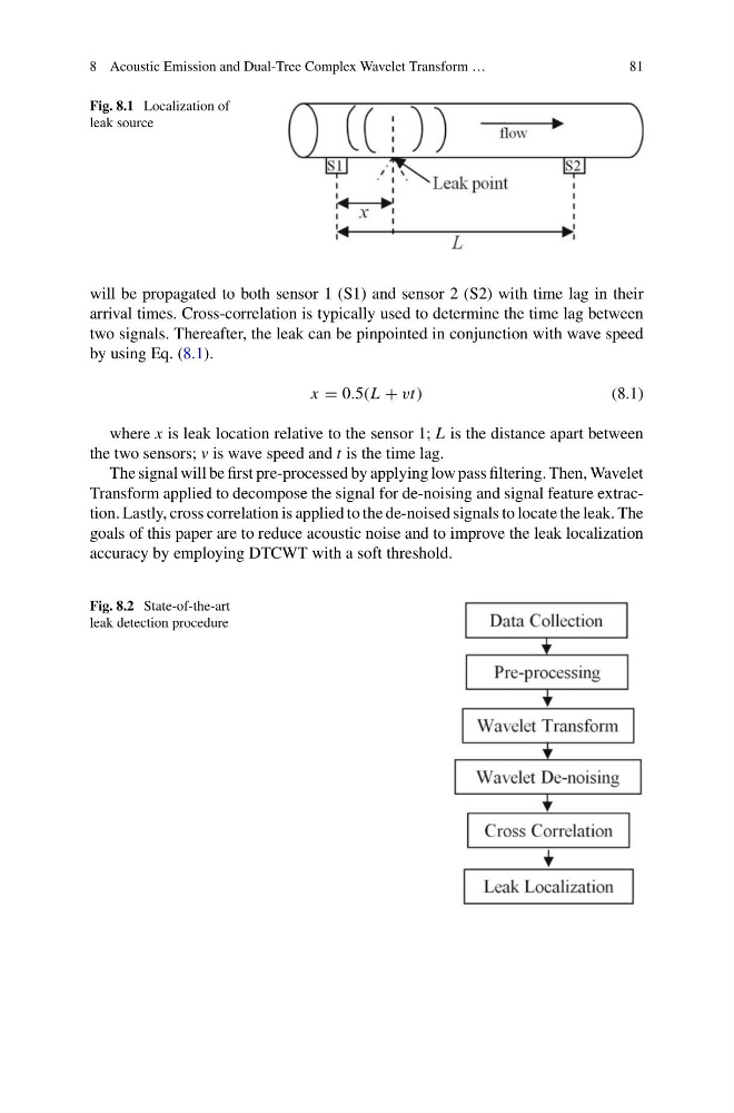
Fig. 8.1 Localization of
leak source
will be propagated to both sensor 1 (S1) and sensor 2 (S2) with time lag in their
arrival times. Cross-correlation is typically used to determine the time lag between
two signals. Thereafter, the leak can be pinpointed in conjunction with wave speed
by using Eq. (8.1).
x = 0.5(L + vt)
(8.1)
where x is leak location relative to the sensor 1; L is the distance apart between
the two sensors; v is wave speed and t is the time lag.
The signal will be first pre-processed by applying low pass filtering. Then, Wavelet
Transform applied to decompose the signal for de-noising and signal feature extraction. Lastly, cross correlation is applied to the de-noised signals to locate the leak. The
goals of this paper are to reduce acoustic noise and to improve the leak localization
accuracy by employing DTCWT with a soft threshold.
Fig. 8.2 State-of-the-art
leak detection procedure
81
Fig. 8.1 Localization of
leak source
will be propagated to both sensor 1 (S1) and sensor 2 (S2) with time lag in their
arrival times. Cross-correlation is typically used to determine the time lag between
two signals. Thereafter, the leak can be pinpointed in conjunction with wave speed
by using Eq. (8.1).
x = 0.5(L + vt)
(8.1)
where x is leak location relative to the sensor 1; L is the distance apart between
the two sensors; v is wave speed and t is the time lag.
The signal will be first pre-processed by applying low pass filtering. Then, Wavelet
Transform applied to decompose the signal for de-noising and signal feature extraction. Lastly, cross correlation is applied to the de-noised signals to locate the leak. The
goals of this paper are to reduce acoustic noise and to improve the leak localization
accuracy by employing DTCWT with a soft threshold.
Fig. 8.2 State-of-the-art
leak detection procedure