

120
4 Chaotic Scattering
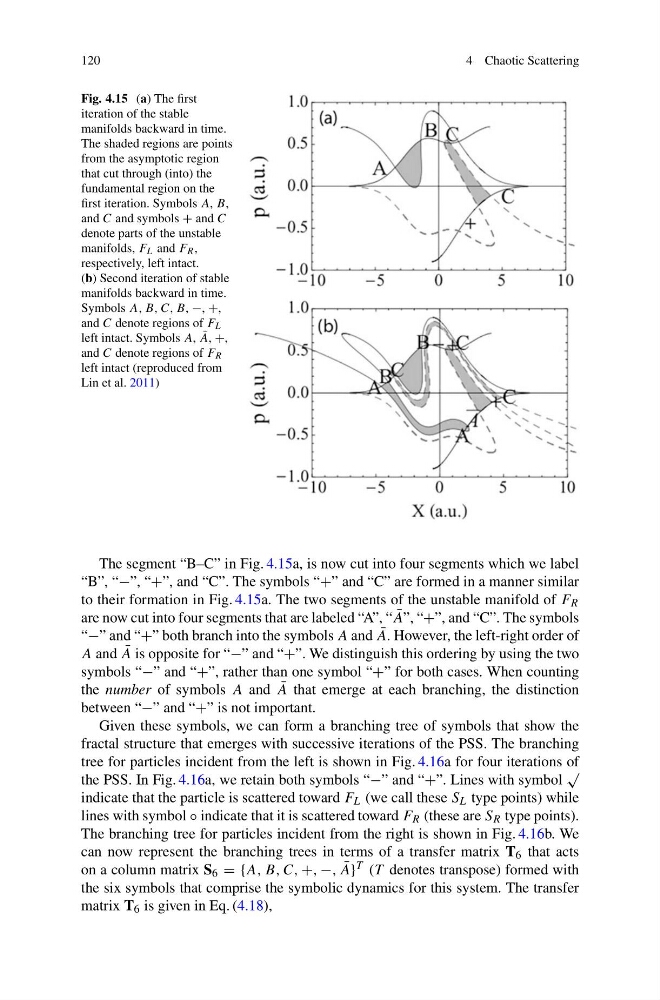
Fig. 4.15 (a) The first
iteration of the stable
manifolds backward in time.
The shaded regions are points
from the asymptotic region
that cut through (into) the
fundamental region on the
first iteration. Symbols A, B,
and C and symbols + and C
denote parts of the unstable
manifolds, F L and F R ,
respectively, left intact.
(b) Second iteration of stable
manifolds backward in time.
Symbols A, B, C, B, −, +,
and C denote regions of F L
left intact. Symbols A, ¯
A, +,
and C denote regions of F R
left intact (reproduced from
Lin et al. 2011)
The segment “B–C” in Fig. 4.15a, is now cut into four segments which we label
“B”, “−”, “+”, and “C”. The symbols “+” and “C” are formed in a manner similar
to their formation in Fig. 4.15a. The two segments of the unstable manifold of F R
are now cut into four segments that are labeled “A”, “ ¯
A”, “+”, and “C”. The symbols
“−” and “+” both branch into the symbols A and ¯
A. However, the left-right order of
A and ¯
A is opposite for “−” and “+”. We distinguish this ordering by using the two
symbols “−” and “+”, rather than one symbol “+” for both cases. When counting
the number of symbols A and ¯
A that emerge at each branching, the distinction
between “−” and “+” is not important.
Given these symbols, we can form a branching tree of symbols that show the
fractal structure that emerges with successive iterations of the PSS. The branching
tree for particles incident from the left is shown in Fig. 4.16a for four iterations of
the PSS. In Fig. 4.16a, we retain both symbols “−” and “+”. Lines with symbol
√
indicate that the particle is scattered toward F L (we call these S L type points) while
lines with symbol ◦ indicate that it is scattered toward F R (these are S R type points).
The branching tree for particles incident from the right is shown in Fig. 4.16b. We
can now represent the branching trees in terms of a transfer matrix T 6 that acts
on a column matrix S 6 = {A, B, C, +, −, ¯
A} T (T denotes transpose) formed with
the six symbols that comprise the symbolic dynamics for this system. The transfer
matrix T 6 is given in Eq. (4.18),
4 Chaotic Scattering
Fig. 4.15 (a) The first
iteration of the stable
manifolds backward in time.
The shaded regions are points
from the asymptotic region
that cut through (into) the
fundamental region on the
first iteration. Symbols A, B,
and C and symbols + and C
denote parts of the unstable
manifolds, F L and F R ,
respectively, left intact.
(b) Second iteration of stable
manifolds backward in time.
Symbols A, B, C, B, −, +,
and C denote regions of F L
left intact. Symbols A, ¯
A, +,
and C denote regions of F R
left intact (reproduced from
Lin et al. 2011)
The segment “B–C” in Fig. 4.15a, is now cut into four segments which we label
“B”, “−”, “+”, and “C”. The symbols “+” and “C” are formed in a manner similar
to their formation in Fig. 4.15a. The two segments of the unstable manifold of F R
are now cut into four segments that are labeled “A”, “ ¯
A”, “+”, and “C”. The symbols
“−” and “+” both branch into the symbols A and ¯
A. However, the left-right order of
A and ¯
A is opposite for “−” and “+”. We distinguish this ordering by using the two
symbols “−” and “+”, rather than one symbol “+” for both cases. When counting
the number of symbols A and ¯
A that emerge at each branching, the distinction
between “−” and “+” is not important.
Given these symbols, we can form a branching tree of symbols that show the
fractal structure that emerges with successive iterations of the PSS. The branching
tree for particles incident from the left is shown in Fig. 4.16a for four iterations of
the PSS. In Fig. 4.16a, we retain both symbols “−” and “+”. Lines with symbol
√
indicate that the particle is scattered toward F L (we call these S L type points) while
lines with symbol ◦ indicate that it is scattered toward F R (these are S R type points).
The branching tree for particles incident from the right is shown in Fig. 4.16b. We
can now represent the branching trees in terms of a transfer matrix T 6 that acts
on a column matrix S 6 = {A, B, C, +, −, ¯
A} T (T denotes transpose) formed with
the six symbols that comprise the symbolic dynamics for this system. The transfer
matrix T 6 is given in Eq. (4.18),