

Ellipsometry Techniques and Its Advanced Applications …
547
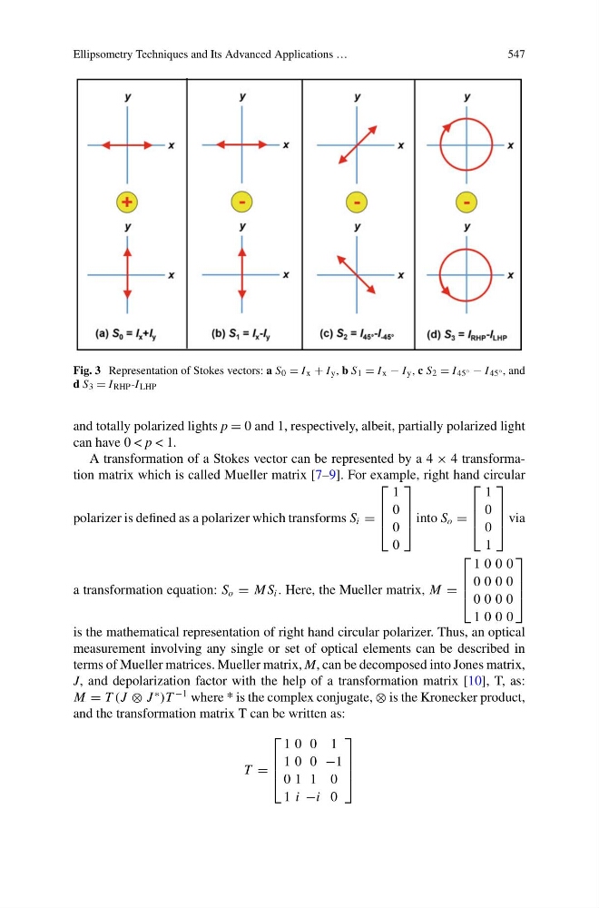
Fig. 3 Representation of Stokes vectors: a S 0 = I x + I y , b S 1 = I x − I y , c S 2 = I 45° − I 45° , and
d S 3 = I RHP -I LHP
and totally polarized lights p = 0 and 1, respectively, albeit, partially polarized light
can have 0 < p < 1.
A transformation of a Stokes vector can be represented by a 4 × 4 transformation matrix which is called Mueller matrix [7–9]. For example, right hand circular
polarizer is defined as a polarizer which transforms S i =
⎡
⎢
⎢
⎣
1
0
0
0
⎤
⎥
⎥
⎦ into S o =
⎡
⎢
⎢
⎣
1
0
0
1
⎤
⎥
⎥
⎦ via
a transformation equation: S o = M S i . Here, the Mueller matrix, M =
⎡
⎢
⎢
⎣
1 0 0 0
0 0 0 0
0 0 0 0
1 0 0 0
⎤
⎥
⎥
⎦
is the mathematical representation of right hand circular polarizer. Thus, an optical
measurement involving any single or set of optical elements can be described in
terms of Mueller matrices. Mueller matrix, M, can be decomposed into Jones matrix,
J, and depolarization factor with the help of a transformation matrix [10], T, as:
M = T (J ⊗ J
∗
)T
−1 where * is the complex conjugate, ⊗ is the Kronecker product,
and the transformation matrix T can be written as:
T =
⎡
⎢
⎢
⎣
1 0 0 1
1 0 0 −1
0 1 1 0
1 i −i 0
⎤
⎥
⎥
⎦
547
Fig. 3 Representation of Stokes vectors: a S 0 = I x + I y , b S 1 = I x − I y , c S 2 = I 45° − I 45° , and
d S 3 = I RHP -I LHP
and totally polarized lights p = 0 and 1, respectively, albeit, partially polarized light
can have 0 < p < 1.
A transformation of a Stokes vector can be represented by a 4 × 4 transformation matrix which is called Mueller matrix [7–9]. For example, right hand circular
polarizer is defined as a polarizer which transforms S i =
⎡
⎢
⎢
⎣
1
0
0
0
⎤
⎥
⎥
⎦ into S o =
⎡
⎢
⎢
⎣
1
0
0
1
⎤
⎥
⎥
⎦ via
a transformation equation: S o = M S i . Here, the Mueller matrix, M =
⎡
⎢
⎢
⎣
1 0 0 0
0 0 0 0
0 0 0 0
1 0 0 0
⎤
⎥
⎥
⎦
is the mathematical representation of right hand circular polarizer. Thus, an optical
measurement involving any single or set of optical elements can be described in
terms of Mueller matrices. Mueller matrix, M, can be decomposed into Jones matrix,
J, and depolarization factor with the help of a transformation matrix [10], T, as:
M = T (J ⊗ J
∗
)T
−1 where * is the complex conjugate, ⊗ is the Kronecker product,
and the transformation matrix T can be written as:
T =
⎡
⎢
⎢
⎣
1 0 0 1
1 0 0 −1
0 1 1 0
1 i −i 0
⎤
⎥
⎥
⎦