

Wavelength Modulation Spectroscopy
347
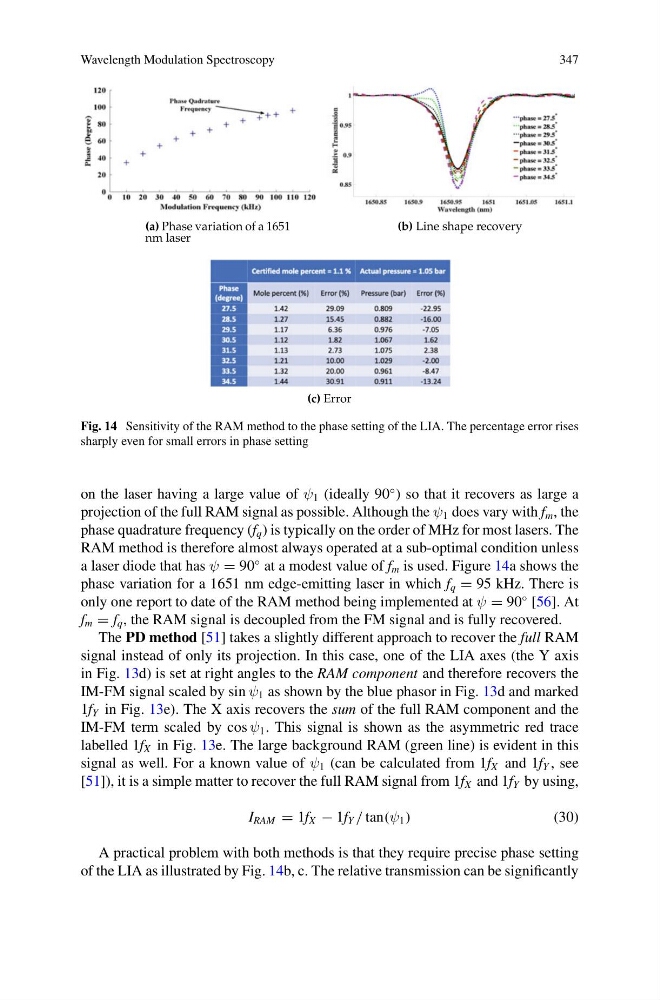
Fig. 14 Sensitivity of the RAM method to the phase setting of the LIA. The percentage error rises
sharply even for small errors in phase setting
on the laser having a large value of ψ 1 (ideally 90
◦ ) so that it recovers as large a
projection of the full RAM signal as possible. Although the ψ 1 does vary with f m , the
phase quadrature frequency (f q ) is typically on the order of MHz for most lasers. The
RAM method is therefore almost always operated at a sub-optimal condition unless
a laser diode that has ψ = 90
◦ at a modest value of f m is used. Figure 14a shows the
phase variation for a 1651 nm edge-emitting laser in which f q = 95 kHz. There is
only one report to date of the RAM method being implemented at ψ = 90
◦ [56]. At
f m = f q , the RAM signal is decoupled from the FM signal and is fully recovered.
The PD method [51] takes a slightly different approach to recover the full RAM
signal instead of only its projection. In this case, one of the LIA axes (the Y axis
in Fig. 13d) is set at right angles to the RAM component and therefore recovers the
IM-FM signal scaled by sin ψ 1 as shown by the blue phasor in Fig. 13d and marked
1f Y in Fig. 13e). The X axis recovers the sum of the full RAM component and the
IM-FM term scaled by cos ψ 1 . This signal is shown as the asymmetric red trace
labelled 1f X in Fig. 13e. The large background RAM (green line) is evident in this
signal as well. For a known value of ψ 1 (can be calculated from 1f X and 1f Y , see
[51]), it is a simple matter to recover the full RAM signal from 1f X and 1f Y by using,
I RAM = 1f X − 1f Y / tan(ψ 1 )
(30)
A practical problem with both methods is that they require precise phase setting
of the LIA as illustrated by Fig. 14b, c. The relative transmission can be significantly
347
Fig. 14 Sensitivity of the RAM method to the phase setting of the LIA. The percentage error rises
sharply even for small errors in phase setting
on the laser having a large value of ψ 1 (ideally 90
◦ ) so that it recovers as large a
projection of the full RAM signal as possible. Although the ψ 1 does vary with f m , the
phase quadrature frequency (f q ) is typically on the order of MHz for most lasers. The
RAM method is therefore almost always operated at a sub-optimal condition unless
a laser diode that has ψ = 90
◦ at a modest value of f m is used. Figure 14a shows the
phase variation for a 1651 nm edge-emitting laser in which f q = 95 kHz. There is
only one report to date of the RAM method being implemented at ψ = 90
◦ [56]. At
f m = f q , the RAM signal is decoupled from the FM signal and is fully recovered.
The PD method [51] takes a slightly different approach to recover the full RAM
signal instead of only its projection. In this case, one of the LIA axes (the Y axis
in Fig. 13d) is set at right angles to the RAM component and therefore recovers the
IM-FM signal scaled by sin ψ 1 as shown by the blue phasor in Fig. 13d and marked
1f Y in Fig. 13e). The X axis recovers the sum of the full RAM component and the
IM-FM term scaled by cos ψ 1 . This signal is shown as the asymmetric red trace
labelled 1f X in Fig. 13e. The large background RAM (green line) is evident in this
signal as well. For a known value of ψ 1 (can be calculated from 1f X and 1f Y , see
[51]), it is a simple matter to recover the full RAM signal from 1f X and 1f Y by using,
I RAM = 1f X − 1f Y / tan(ψ 1 )
(30)
A practical problem with both methods is that they require precise phase setting
of the LIA as illustrated by Fig. 14b, c. The relative transmission can be significantly