

Cavity Ring-Down Spectroscopy
291
billion by volume, 10
–9 ) or pptv (parts per trillion by volume, 10
–12 ). However, pressures broadening of absorption spectra need to be considered because the detection
limits are usually represented at 1 atmospheric pressure in a bulk gas. In addition to
that, the sensitivity can be expressed by a term, so-called, NEA i.e. noise-equivalent
absorption co-efficient (NEA) which is given by:
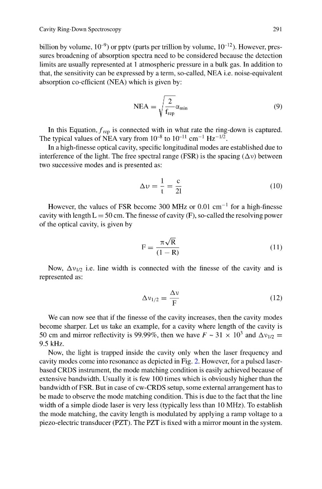
NEA =
2
f rep
α min
(9)
In this Equation, f rep is connected with in what rate the ring-down is captured.
The typical values of NEA vary from 10
–8 to 10
–11 cm
−1 Hz
−1/2 .
In a high-finesse optical cavity, specific longitudinal modes are established due to
interference of the light. The free spectral range (FSR) is the spacing (ν) between
two successive modes and is presented as:
υ =
1
t
=
c
2l
(10)
However, the values of FSR become 300 MHz or 0.01 cm
−1 for a high-finesse
cavity with length L = 50 cm. The finesse of cavity (F), so-called the resolving power
of the optical cavity, is given by
F =
π
√
R
(1 − R)
(11)
Now, ν 1/2 i.e. line width is connected with the finesse of the cavity and is
represented as:
ν 1/2 =
ν
F
(12)
We can now see that if the finesse of the cavity increases, then the cavity modes
become sharper. Let us take an example, for a cavity where length of the cavity is
50 cm and mirror reflectivity is 99.99%, then we have F ~ 31 × 10
3 and ν 1/2 =
9.5 kHz.
Now, the light is trapped inside the cavity only when the laser frequency and
cavity modes come into resonance as depicted in Fig. 2. However, for a pulsed laserbased CRDS instrument, the mode matching condition is easily achieved because of
extensive bandwidth. Usually it is few 100 times which is obviously higher than the
bandwidth of FSR. But in case of cw-CRDS setup, some external arrangement has to
be made to observe the mode matching condition. This is due to the fact that the line
width of a simple diode laser is very less (typically less than 10 MHz). To establish
the mode matching, the cavity length is modulated by applying a ramp voltage to a
piezo-electric transducer (PZT). The PZT is fixed with a mirror mount in the system.
291
billion by volume, 10
–9 ) or pptv (parts per trillion by volume, 10
–12 ). However, pressures broadening of absorption spectra need to be considered because the detection
limits are usually represented at 1 atmospheric pressure in a bulk gas. In addition to
that, the sensitivity can be expressed by a term, so-called, NEA i.e. noise-equivalent
absorption co-efficient (NEA) which is given by:
NEA =
2
f rep
α min
(9)
In this Equation, f rep is connected with in what rate the ring-down is captured.
The typical values of NEA vary from 10
–8 to 10
–11 cm
−1 Hz
−1/2 .
In a high-finesse optical cavity, specific longitudinal modes are established due to
interference of the light. The free spectral range (FSR) is the spacing (ν) between
two successive modes and is presented as:
υ =
1
t
=
c
2l
(10)
However, the values of FSR become 300 MHz or 0.01 cm
−1 for a high-finesse
cavity with length L = 50 cm. The finesse of cavity (F), so-called the resolving power
of the optical cavity, is given by
F =
π
√
R
(1 − R)
(11)
Now, ν 1/2 i.e. line width is connected with the finesse of the cavity and is
represented as:
ν 1/2 =
ν
F
(12)
We can now see that if the finesse of the cavity increases, then the cavity modes
become sharper. Let us take an example, for a cavity where length of the cavity is
50 cm and mirror reflectivity is 99.99%, then we have F ~ 31 × 10
3 and ν 1/2 =
9.5 kHz.
Now, the light is trapped inside the cavity only when the laser frequency and
cavity modes come into resonance as depicted in Fig. 2. However, for a pulsed laserbased CRDS instrument, the mode matching condition is easily achieved because of
extensive bandwidth. Usually it is few 100 times which is obviously higher than the
bandwidth of FSR. But in case of cw-CRDS setup, some external arrangement has to
be made to observe the mode matching condition. This is due to the fact that the line
width of a simple diode laser is very less (typically less than 10 MHz). To establish
the mode matching, the cavity length is modulated by applying a ramp voltage to a
piezo-electric transducer (PZT). The PZT is fixed with a mirror mount in the system.