

Tip-Enhanced Raman Spectroscopy
215
3 Instrumentation for TERS
3.1 Experimental Setup
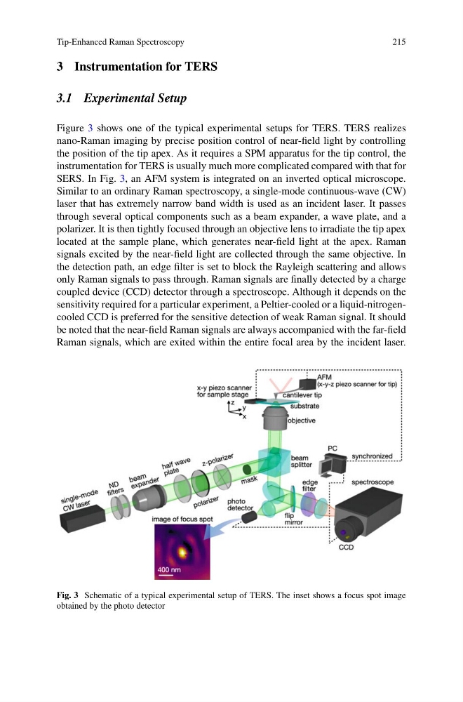
Figure 3 shows one of the typical experimental setups for TERS. TERS realizes
nano-Raman imaging by precise position control of near-field light by controlling
the position of the tip apex. As it requires a SPM apparatus for the tip control, the
instrumentation for TERS is usually much more complicated compared with that for
SERS. In Fig. 3, an AFM system is integrated on an inverted optical microscope.
Similar to an ordinary Raman spectroscopy, a single-mode continuous-wave (CW)
laser that has extremely narrow band width is used as an incident laser. It passes
through several optical components such as a beam expander, a wave plate, and a
polarizer. It is then tightly focused through an objective lens to irradiate the tip apex
located at the sample plane, which generates near-field light at the apex. Raman
signals excited by the near-field light are collected through the same objective. In
the detection path, an edge filter is set to block the Rayleigh scattering and allows
only Raman signals to pass through. Raman signals are finally detected by a charge
coupled device (CCD) detector through a spectroscope. Although it depends on the
sensitivity required for a particular experiment, a Peltier-cooled or a liquid-nitrogencooled CCD is preferred for the sensitive detection of weak Raman signal. It should
be noted that the near-field Raman signals are always accompanied with the far-field
Raman signals, which are exited within the entire focal area by the incident laser.
Fig. 3 Schematic of a typical experimental setup of TERS. The inset shows a focus spot image
obtained by the photo detector
215
3 Instrumentation for TERS
3.1 Experimental Setup
Figure 3 shows one of the typical experimental setups for TERS. TERS realizes
nano-Raman imaging by precise position control of near-field light by controlling
the position of the tip apex. As it requires a SPM apparatus for the tip control, the
instrumentation for TERS is usually much more complicated compared with that for
SERS. In Fig. 3, an AFM system is integrated on an inverted optical microscope.
Similar to an ordinary Raman spectroscopy, a single-mode continuous-wave (CW)
laser that has extremely narrow band width is used as an incident laser. It passes
through several optical components such as a beam expander, a wave plate, and a
polarizer. It is then tightly focused through an objective lens to irradiate the tip apex
located at the sample plane, which generates near-field light at the apex. Raman
signals excited by the near-field light are collected through the same objective. In
the detection path, an edge filter is set to block the Rayleigh scattering and allows
only Raman signals to pass through. Raman signals are finally detected by a charge
coupled device (CCD) detector through a spectroscope. Although it depends on the
sensitivity required for a particular experiment, a Peltier-cooled or a liquid-nitrogencooled CCD is preferred for the sensitive detection of weak Raman signal. It should
be noted that the near-field Raman signals are always accompanied with the far-field
Raman signals, which are exited within the entire focal area by the incident laser.
Fig. 3 Schematic of a typical experimental setup of TERS. The inset shows a focus spot image
obtained by the photo detector