

190
B. P. Majee and A. K. Mishra
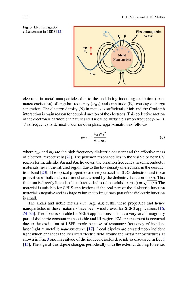
Fig. 3 Electromagnetic
enhancement in SERS [15]
E 0
Electromagnetic
Wave
E loc
+ + +
+
−
−
−
Metal
Nanoparticle
−
+
−
electrons in metal nanoparticles due to the oscillating incoming excitation (resonance excitation) of angular frequency (ω inc ) and amplitude (E 0 ) causing a charge
separation. The electron density (N) in metals is sufficiently high and the Coulomb
interaction is main reason for coupled motion of the electrons. This collective motion
of the electron is harmonic in nature and it is called surface plasmon frequency (ω SP ).
This frequency is defined under random phase approximation as followsω SP =
4π N e
2
∈ ∞ m e
(6)
where ∈ ∞ and m e are the high frequency dielectric constant and the effective mass
of electron, respectively [22]. The plasmon resonance lies in the visible or near UV
region for metals like Ag and Au, however, the plasmon frequency in semiconductor
materials lies in the infrared region due to the low density of electrons in the conduction band [23]. The optical properties are very crucial in SERS detection and these
properties of bulk materials are characterized by the dielectric function ∈ (ω). This
function is directly linked to the refractive index of materials i.e. n(ω) =
√
∈ (ω).The
material is suitable for SERS applications if the real part of the dielectric function
material is negative and has large value and its imaginary part of the dielectric function
is small.
The alkali and noble metals (Cu, Ag, Au) fulfill these properties and hence
nanoparticles of these materials have been widely used for SERS applications [16,
24–26]. The silver is suitable for SERS applications as it has a very small imaginary
part of dielectric constant in the visible and IR region. EM enhancement is occurred
due to the excitation of LSPR mode because of resonance frequency of incident
laser light at metallic nanostructures [17]. Local dipoles are created upon incident
light which enhances the localized electric field around the metal nanostructures as
shown in Fig. 3 and magnitude of the induced dipoles depends as discussed in Eq. 1
[15]. The sign of this dipole changes periodically with the external driving force i.e.
B. P. Majee and A. K. Mishra
Fig. 3 Electromagnetic
enhancement in SERS [15]
E 0
Electromagnetic
Wave
E loc
+ + +
+
−
−
−
Metal
Nanoparticle
−
+
−
electrons in metal nanoparticles due to the oscillating incoming excitation (resonance excitation) of angular frequency (ω inc ) and amplitude (E 0 ) causing a charge
separation. The electron density (N) in metals is sufficiently high and the Coulomb
interaction is main reason for coupled motion of the electrons. This collective motion
of the electron is harmonic in nature and it is called surface plasmon frequency (ω SP ).
This frequency is defined under random phase approximation as followsω SP =
4π N e
2
∈ ∞ m e
(6)
where ∈ ∞ and m e are the high frequency dielectric constant and the effective mass
of electron, respectively [22]. The plasmon resonance lies in the visible or near UV
region for metals like Ag and Au, however, the plasmon frequency in semiconductor
materials lies in the infrared region due to the low density of electrons in the conduction band [23]. The optical properties are very crucial in SERS detection and these
properties of bulk materials are characterized by the dielectric function ∈ (ω). This
function is directly linked to the refractive index of materials i.e. n(ω) =
√
∈ (ω).The
material is suitable for SERS applications if the real part of the dielectric function
material is negative and has large value and its imaginary part of the dielectric function
is small.
The alkali and noble metals (Cu, Ag, Au) fulfill these properties and hence
nanoparticles of these materials have been widely used for SERS applications [16,
24–26]. The silver is suitable for SERS applications as it has a very small imaginary
part of dielectric constant in the visible and IR region. EM enhancement is occurred
due to the excitation of LSPR mode because of resonance frequency of incident
laser light at metallic nanostructures [17]. Local dipoles are created upon incident
light which enhances the localized electric field around the metal nanostructures as
shown in Fig. 3 and magnitude of the induced dipoles depends as discussed in Eq. 1
[15]. The sign of this dipole changes periodically with the external driving force i.e.