

130
S. Banerjee et al.
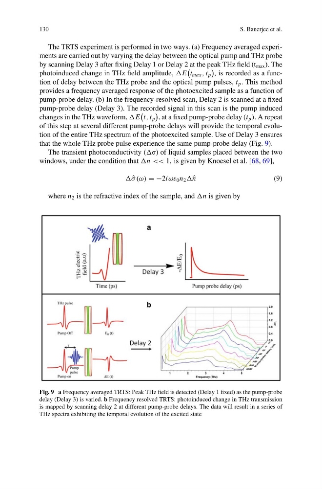
The TRTS experiment is performed in two ways. (a) Frequency averaged experiments are carried out by varying the delay between the optical pump and THz probe
by scanning Delay 3 after fixing Delay 1 or Delay 2 at the peak THz field (t max ). The
photoinduced change in THz field amplitude, E
t max , t p
, is recorded as a function of delay between the THz probe and the optical pump pulses, t p . This method
provides a frequency averaged response of the photoexcited sample as a function of
pump-probe delay. (b) In the frequency-resolved scan, Delay 2 is scanned at a fixed
pump-probe delay (Delay 3). The recorded signal in this scan is the pump induced
changes in the THz waveform, E
t, t p
, at a fixed pump-probe delay (t p ). A repeat
of this step at several different pump-probe delays will provide the temporal evolution of the entire THz spectrum of the photoexcited sample. Use of Delay 3 ensures
that the whole THz probe pulse experience the same pump-probe delay (Fig. 9).
The transient photoconductivity (σ) of liquid samples placed between the two
windows, under the condition that n << 1, is given by Knoesel et al. [68, 69],
ˆ
σ (ω) = −2iωε 0 n 2 ˆ
n
(9)
where n 2 is the refractive index of the sample, and n is given by
Fig. 9 a Frequency averaged TRTS: Peak THz field is detected (Delay 1 fixed) as the pump-probe
delay (Delay 3) is varied. b Frequency resolved TRTS: photoinduced change in THz transmission
is mapped by scanning delay 2 at different pump-probe delays. The data will result in a series of
THz spectra exhibiting the temporal evolution of the excited state
S. Banerjee et al.
The TRTS experiment is performed in two ways. (a) Frequency averaged experiments are carried out by varying the delay between the optical pump and THz probe
by scanning Delay 3 after fixing Delay 1 or Delay 2 at the peak THz field (t max ). The
photoinduced change in THz field amplitude, E
t max , t p
, is recorded as a function of delay between the THz probe and the optical pump pulses, t p . This method
provides a frequency averaged response of the photoexcited sample as a function of
pump-probe delay. (b) In the frequency-resolved scan, Delay 2 is scanned at a fixed
pump-probe delay (Delay 3). The recorded signal in this scan is the pump induced
changes in the THz waveform, E
t, t p
, at a fixed pump-probe delay (t p ). A repeat
of this step at several different pump-probe delays will provide the temporal evolution of the entire THz spectrum of the photoexcited sample. Use of Delay 3 ensures
that the whole THz probe pulse experience the same pump-probe delay (Fig. 9).
The transient photoconductivity (σ) of liquid samples placed between the two
windows, under the condition that n << 1, is given by Knoesel et al. [68, 69],
ˆ
σ (ω) = −2iωε 0 n 2 ˆ
n
(9)
where n 2 is the refractive index of the sample, and n is given by
Fig. 9 a Frequency averaged TRTS: Peak THz field is detected (Delay 1 fixed) as the pump-probe
delay (Delay 3) is varied. b Frequency resolved TRTS: photoinduced change in THz transmission
is mapped by scanning delay 2 at different pump-probe delays. The data will result in a series of
THz spectra exhibiting the temporal evolution of the excited state