

Broadband Terahertz Spectroscopy
129
The Fresnel reflection and transmission losses should be considered while
extracting the complex refractive index ( ˜
n(ω) = n re (ω) + in im (ω)) from T (ω) and
ϕ(ω) using an iterative method. Further, using k (extinction coefficient) and n (refractive index), other optical constants such as dielectric function, conductivity, etc. can
be calculated.
For opaque materials or samples with very strong THz absorption, THz-TDS in
reflection geometry is generally preferred. Similar to the transmission geometry, the
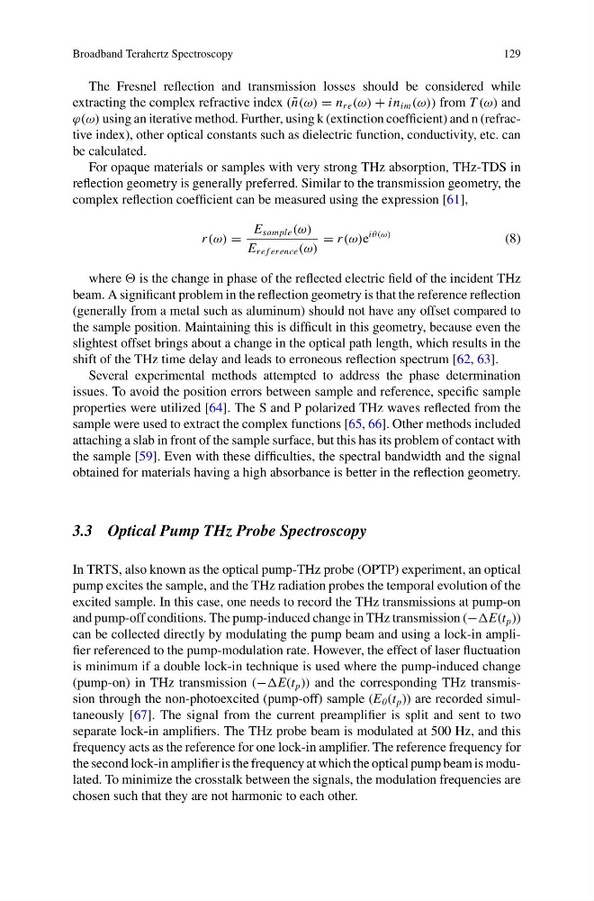
complex reflection coefficient can be measured using the expression [61],
r (ω) =
E sample (ω)
E re f erence (ω)
= r (ω)e
iθ(ω)
(8)
where is the change in phase of the reflected electric field of the incident THz
beam. A significant problem in the reflection geometry is that the reference reflection
(generally from a metal such as aluminum) should not have any offset compared to
the sample position. Maintaining this is difficult in this geometry, because even the
slightest offset brings about a change in the optical path length, which results in the
shift of the THz time delay and leads to erroneous reflection spectrum [62, 63].
Several experimental methods attempted to address the phase determination
issues. To avoid the position errors between sample and reference, specific sample
properties were utilized [64]. The S and P polarized THz waves reflected from the
sample were used to extract the complex functions [65, 66]. Other methods included
attaching a slab in front of the sample surface, but this has its problem of contact with
the sample [59]. Even with these difficulties, the spectral bandwidth and the signal
obtained for materials having a high absorbance is better in the reflection geometry.
3.3 Optical Pump THz Probe Spectroscopy
In TRTS, also known as the optical pump-THz probe (OPTP) experiment, an optical
pump excites the sample, and the THz radiation probes the temporal evolution of the
excited sample. In this case, one needs to record the THz transmissions at pump-on
and pump-off conditions. The pump-induced change in THz transmission (−E(t p ))
can be collected directly by modulating the pump beam and using a lock-in amplifier referenced to the pump-modulation rate. However, the effect of laser fluctuation
is minimum if a double lock-in technique is used where the pump-induced change
(pump-on) in THz transmission (−E(t p )) and the corresponding THz transmission through the non-photoexcited (pump-off) sample (E 0 (t p )) are recorded simultaneously [67]. The signal from the current preamplifier is split and sent to two
separate lock-in amplifiers. The THz probe beam is modulated at 500 Hz, and this
frequency acts as the reference for one lock-in amplifier. The reference frequency for
the second lock-in amplifier is the frequency at which the optical pump beam is modulated. To minimize the crosstalk between the signals, the modulation frequencies are
chosen such that they are not harmonic to each other.
129
The Fresnel reflection and transmission losses should be considered while
extracting the complex refractive index ( ˜
n(ω) = n re (ω) + in im (ω)) from T (ω) and
ϕ(ω) using an iterative method. Further, using k (extinction coefficient) and n (refractive index), other optical constants such as dielectric function, conductivity, etc. can
be calculated.
For opaque materials or samples with very strong THz absorption, THz-TDS in
reflection geometry is generally preferred. Similar to the transmission geometry, the
complex reflection coefficient can be measured using the expression [61],
r (ω) =
E sample (ω)
E re f erence (ω)
= r (ω)e
iθ(ω)
(8)
where is the change in phase of the reflected electric field of the incident THz
beam. A significant problem in the reflection geometry is that the reference reflection
(generally from a metal such as aluminum) should not have any offset compared to
the sample position. Maintaining this is difficult in this geometry, because even the
slightest offset brings about a change in the optical path length, which results in the
shift of the THz time delay and leads to erroneous reflection spectrum [62, 63].
Several experimental methods attempted to address the phase determination
issues. To avoid the position errors between sample and reference, specific sample
properties were utilized [64]. The S and P polarized THz waves reflected from the
sample were used to extract the complex functions [65, 66]. Other methods included
attaching a slab in front of the sample surface, but this has its problem of contact with
the sample [59]. Even with these difficulties, the spectral bandwidth and the signal
obtained for materials having a high absorbance is better in the reflection geometry.
3.3 Optical Pump THz Probe Spectroscopy
In TRTS, also known as the optical pump-THz probe (OPTP) experiment, an optical
pump excites the sample, and the THz radiation probes the temporal evolution of the
excited sample. In this case, one needs to record the THz transmissions at pump-on
and pump-off conditions. The pump-induced change in THz transmission (−E(t p ))
can be collected directly by modulating the pump beam and using a lock-in amplifier referenced to the pump-modulation rate. However, the effect of laser fluctuation
is minimum if a double lock-in technique is used where the pump-induced change
(pump-on) in THz transmission (−E(t p )) and the corresponding THz transmission through the non-photoexcited (pump-off) sample (E 0 (t p )) are recorded simultaneously [67]. The signal from the current preamplifier is split and sent to two
separate lock-in amplifiers. The THz probe beam is modulated at 500 Hz, and this
frequency acts as the reference for one lock-in amplifier. The reference frequency for
the second lock-in amplifier is the frequency at which the optical pump beam is modulated. To minimize the crosstalk between the signals, the modulation frequencies are
chosen such that they are not harmonic to each other.