

24
2 Active and Passive Micromixers
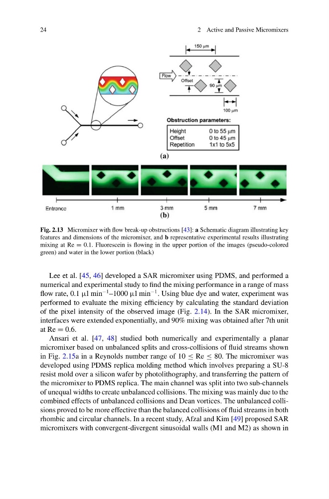
Fig. 2.13 Micromixer with flow break-up obstructions [43]: a Schematic diagram illustrating key
features and dimensions of the micromixer, and b representative experimental results illustrating
mixing at Re = 0.1. Fluorescein is flowing in the upper portion of the images (pseudo-colored
green) and water in the lower portion (black)
Lee et al. [45, 46] developed a SAR micromixer using PDMS, and performed a
numerical and experimental study to find the mixing performance in a range of mass
flow rate, 0.1 μl min
−1 –1000 μl min
−1 . Using blue dye and water, experiment was
performed to evaluate the mixing efficiency by calculating the standard deviation
of the pixel intensity of the observed image (Fig. 2.14). In the SAR micromixer,
interfaces were extended exponentially, and 90% mixing was obtained after 7th unit
at Re = 0.6.
Ansari et al. [47, 48] studied both numerically and experimentally a planar
micromixer based on unbalanced splits and cross-collisions of fluid streams shown
in Fig. 2.15a in a Reynolds number range of 10 ≤ Re ≤ 80. The micromixer was
developed using PDMS replica molding method which involves preparing a SU-8
resist mold over a silicon wafer by photolithography, and transferring the pattern of
the micromixer to PDMS replica. The main channel was split into two sub-channels
of unequal widths to create unbalanced collisions. The mixing was mainly due to the
combined effects of unbalanced collisions and Dean vortices. The unbalanced collisions proved to be more effective than the balanced collisions of fluid streams in both
rhombic and circular channels. In a recent study, Afzal and Kim [49] proposed SAR
micromixers with convergent-divergent sinusoidal walls (M1 and M2) as shown in
2 Active and Passive Micromixers
Fig. 2.13 Micromixer with flow break-up obstructions [43]: a Schematic diagram illustrating key
features and dimensions of the micromixer, and b representative experimental results illustrating
mixing at Re = 0.1. Fluorescein is flowing in the upper portion of the images (pseudo-colored
green) and water in the lower portion (black)
Lee et al. [45, 46] developed a SAR micromixer using PDMS, and performed a
numerical and experimental study to find the mixing performance in a range of mass
flow rate, 0.1 μl min
−1 –1000 μl min
−1 . Using blue dye and water, experiment was
performed to evaluate the mixing efficiency by calculating the standard deviation
of the pixel intensity of the observed image (Fig. 2.14). In the SAR micromixer,
interfaces were extended exponentially, and 90% mixing was obtained after 7th unit
at Re = 0.6.
Ansari et al. [47, 48] studied both numerically and experimentally a planar
micromixer based on unbalanced splits and cross-collisions of fluid streams shown
in Fig. 2.15a in a Reynolds number range of 10 ≤ Re ≤ 80. The micromixer was
developed using PDMS replica molding method which involves preparing a SU-8
resist mold over a silicon wafer by photolithography, and transferring the pattern of
the micromixer to PDMS replica. The main channel was split into two sub-channels
of unequal widths to create unbalanced collisions. The mixing was mainly due to the
combined effects of unbalanced collisions and Dean vortices. The unbalanced collisions proved to be more effective than the balanced collisions of fluid streams in both
rhombic and circular channels. In a recent study, Afzal and Kim [49] proposed SAR
micromixers with convergent-divergent sinusoidal walls (M1 and M2) as shown in