

4.2 Angular Coordinates Measurement Methods
71
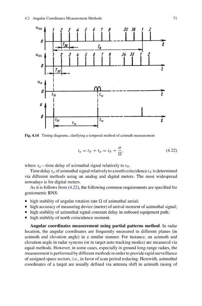
Fig. 4.14 Timing diagrams, clarifying a temporal method of azimuth measurement
t α = t N + τ α = t N +
α
,
(4.22)
where τ α —time delay of azimuthal signal relatively to t N .
Time delay τ α of azimuthal signal relatively to a north coincidence t N is determined
via different methods using an analog and digital meters. The most widespread
nowadays is for digital meters.
As it is follows from (4.22), the following common requirements are specified for
goniometric RNS:
• high stability of angular rotation rate of azimuthal aerial;
• high accuracy of measuring device (meter) of arrival moment of azimuthal signal;
• high stability of azimuthal signal constant delay in onboard equipment path;
• high stability of north coincidence moment.
Angular coordinates measurement using partial patterns method. In radar
location, the angular coordinates are frequently measured in different planes (in
azimuth and elevation angle) in a similar manner. For instance, an azimuth and
elevation angle in radar systems (or in target auto tracking modes) are measured via
equal methods. However, in some cases, especially in ground long-range radars, the
measurement is performed by different methods in order to provide rapid surveillance
of assigned space sectors, i.e., in favor of scan period reducing. Herewith, azimuthal
coordinates of a target are usually defined via antenna shift in azimuth (using of
71
Fig. 4.14 Timing diagrams, clarifying a temporal method of azimuth measurement
t α = t N + τ α = t N +
α
,
(4.22)
where τ α —time delay of azimuthal signal relatively to t N .
Time delay τ α of azimuthal signal relatively to a north coincidence t N is determined
via different methods using an analog and digital meters. The most widespread
nowadays is for digital meters.
As it is follows from (4.22), the following common requirements are specified for
goniometric RNS:
• high stability of angular rotation rate of azimuthal aerial;
• high accuracy of measuring device (meter) of arrival moment of azimuthal signal;
• high stability of azimuthal signal constant delay in onboard equipment path;
• high stability of north coincidence moment.
Angular coordinates measurement using partial patterns method. In radar
location, the angular coordinates are frequently measured in different planes (in
azimuth and elevation angle) in a similar manner. For instance, an azimuth and
elevation angle in radar systems (or in target auto tracking modes) are measured via
equal methods. However, in some cases, especially in ground long-range radars, the
measurement is performed by different methods in order to provide rapid surveillance
of assigned space sectors, i.e., in favor of scan period reducing. Herewith, azimuthal
coordinates of a target are usually defined via antenna shift in azimuth (using of