

70
4 Measuring Principles and Techniques …
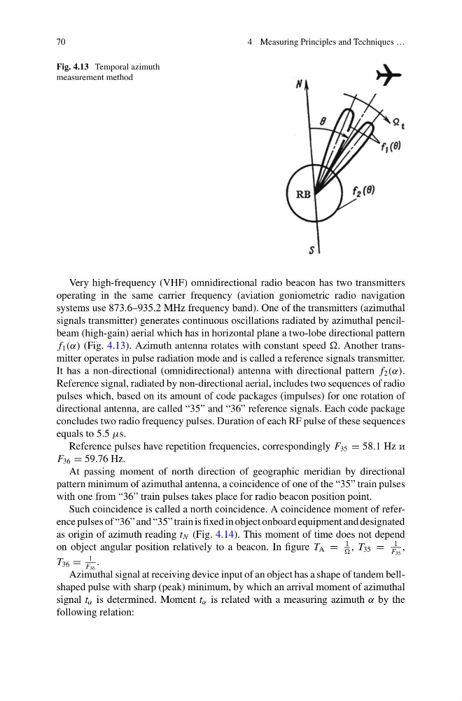
Fig. 4.13 Temporal azimuth
measurement method
Very high-frequency (VHF) omnidirectional radio beacon has two transmitters
operating in the same carrier frequency (aviation goniometric radio navigation
systems use 873.6–935.2 MHz frequency band). One of the transmitters (azimuthal
signals transmitter) generates continuous oscillations radiated by azimuthal pencilbeam (high-gain) aerial which has in horizontal plane a two-lobe directional pattern
f 1 (α) (Fig. 4.13). Azimuth antenna rotates with constant speed . Another transmitter operates in pulse radiation mode and is called a reference signals transmitter.
It has a non-directional (omnidirectional) antenna with directional pattern f 2 (α).
Reference signal, radiated by non-directional aerial, includes two sequences of radio
pulses which, based on its amount of code packages (impulses) for one rotation of
directional antenna, are called “35” and “36” reference signals. Each code package
concludes two radio frequency pulses. Duration of each RF pulse of these sequences
equals to 5.5 μs.
Reference pulses have repetition frequencies, correspondingly F 35 = 58.1 Hz i
F 36 = 59.76 Hz.
At passing moment of north direction of geographic meridian by directional
pattern minimum of azimuthal antenna, a coincidence of one of the “35” train pulses
with one from “36” train pulses takes place for radio beacon position point.
Such coincidence is called a north coincidence. A coincidence moment of reference pulses of “36” and “35” train is fixed in object onboard equipment and designated
as origin of azimuth reading t N (Fig. 4.14). This moment of time does not depend
on object angular position relatively to a beacon. In figure T A =
1
, T 35 =
1
F 35
,
T 36 =
1
F 36
.
Azimuthal signal at receiving device input of an object has a shape of tandem bellshaped pulse with sharp (peak) minimum, by which an arrival moment of azimuthal
signal t α is determined. Moment t α is related with a measuring azimuth α by the
following relation:
4 Measuring Principles and Techniques …
Fig. 4.13 Temporal azimuth
measurement method
Very high-frequency (VHF) omnidirectional radio beacon has two transmitters
operating in the same carrier frequency (aviation goniometric radio navigation
systems use 873.6–935.2 MHz frequency band). One of the transmitters (azimuthal
signals transmitter) generates continuous oscillations radiated by azimuthal pencilbeam (high-gain) aerial which has in horizontal plane a two-lobe directional pattern
f 1 (α) (Fig. 4.13). Azimuth antenna rotates with constant speed . Another transmitter operates in pulse radiation mode and is called a reference signals transmitter.
It has a non-directional (omnidirectional) antenna with directional pattern f 2 (α).
Reference signal, radiated by non-directional aerial, includes two sequences of radio
pulses which, based on its amount of code packages (impulses) for one rotation of
directional antenna, are called “35” and “36” reference signals. Each code package
concludes two radio frequency pulses. Duration of each RF pulse of these sequences
equals to 5.5 μs.
Reference pulses have repetition frequencies, correspondingly F 35 = 58.1 Hz i
F 36 = 59.76 Hz.
At passing moment of north direction of geographic meridian by directional
pattern minimum of azimuthal antenna, a coincidence of one of the “35” train pulses
with one from “36” train pulses takes place for radio beacon position point.
Such coincidence is called a north coincidence. A coincidence moment of reference pulses of “36” and “35” train is fixed in object onboard equipment and designated
as origin of azimuth reading t N (Fig. 4.14). This moment of time does not depend
on object angular position relatively to a beacon. In figure T A =
1
, T 35 =
1
F 35
,
T 36 =
1
F 36
.
Azimuthal signal at receiving device input of an object has a shape of tandem bellshaped pulse with sharp (peak) minimum, by which an arrival moment of azimuthal
signal t α is determined. Moment t α is related with a measuring azimuth α by the
following relation: