

4.2 Angular Coordinates Measurement Methods
67
Fig. 4.10 Illustration of
amplitudes comparison
method
processes is a different target signal intensity (more precisely, signal-to-noise ratio)
in different time periods. In conditions of random interference, a parallel comparison
circuit has fundamental advantages before consequent circuit. Indeed, at forming of
equisignal direction by consequent (single channel) method, some time passes T s
from a moment of signal receiving by one beam up to a moment of signal receiving by
another one (Fig. 4.11a). Switching time T s is required for antenna exciter (feed) shift
from one position into another in a plane where an angle measuring is performed. To
create a spatial equisignal direction (angles measuring in two perpendicular planes),
in this case an exciter is rotated around antenna focal axis.
As for pulse radar in one beam position, a one pulse train is received, and in another
beam—another one. To create an equisignal direction, it is minimally necessary to
have two pulses of reflected energy which will be apart at a time of switching T s and
are to be compared in intensity using inertial circuit. In conditions of fluctuations,
these two pulses could not be equal.
At forming of equisignal direction by parallel (dual-channel) method (Fig. 4.11b),
two stationary radiators exist, symmetrically shifted in a bearing plane relatively to a
focal axis of antenna mirror. Two simultaneously acting directional patterns are originated, on each of which the same “sample” of high-frequency reflected energy is
received, separately amplified by two receiving channels. As for pulse radar, the same
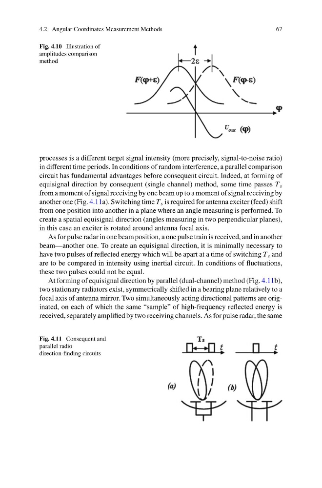
Fig. 4.11 Consequent and
parallel radio
direction-finding circuits
67
Fig. 4.10 Illustration of
amplitudes comparison
method
processes is a different target signal intensity (more precisely, signal-to-noise ratio)
in different time periods. In conditions of random interference, a parallel comparison
circuit has fundamental advantages before consequent circuit. Indeed, at forming of
equisignal direction by consequent (single channel) method, some time passes T s
from a moment of signal receiving by one beam up to a moment of signal receiving by
another one (Fig. 4.11a). Switching time T s is required for antenna exciter (feed) shift
from one position into another in a plane where an angle measuring is performed. To
create a spatial equisignal direction (angles measuring in two perpendicular planes),
in this case an exciter is rotated around antenna focal axis.
As for pulse radar in one beam position, a one pulse train is received, and in another
beam—another one. To create an equisignal direction, it is minimally necessary to
have two pulses of reflected energy which will be apart at a time of switching T s and
are to be compared in intensity using inertial circuit. In conditions of fluctuations,
these two pulses could not be equal.
At forming of equisignal direction by parallel (dual-channel) method (Fig. 4.11b),
two stationary radiators exist, symmetrically shifted in a bearing plane relatively to a
focal axis of antenna mirror. Two simultaneously acting directional patterns are originated, on each of which the same “sample” of high-frequency reflected energy is
received, separately amplified by two receiving channels. As for pulse radar, the same
Fig. 4.11 Consequent and
parallel radio
direction-finding circuits