

36
3 Radar Targets and Its Reflecting Properties
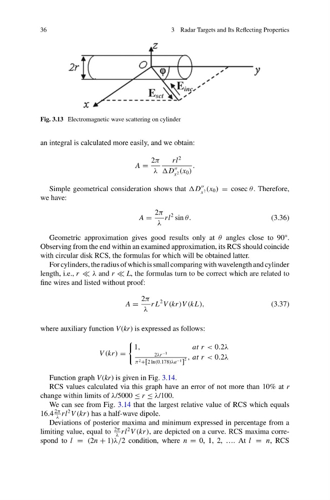
Fig. 3.13 Electromagnetic wave scattering on cylinder
an integral is calculated more easily, and we obtain:
A =
2π
λ
rl
2
D
x 2 (x 0 )
.
Simple geometrical consideration shows that D
x 2 (x 0 ) = cosec θ . Therefore,
we have:
A =
2π
λ
rl
2 sin θ.
(3.36)
Geometric approximation gives good results only at θ angles close to 90°.
Observing from the end within an examined approximation, its RCS should coincide
with circular disk RCS, the formulas for which will be obtained latter.
For cylinders, the radius of which is small comparing with wavelength and cylinder
length, i.e., r λ and r L, the formulas turn to be correct which are related to
fine wires and listed without proof:
A =
2π
λ
r L
2 V (kr)V (k L),
(3.37)
where auxiliary function V (kr) is expressed as follows:
V (kr) =
1,
at r < 0.2λ
2λr
−1
π 2 +[2 ln(0.178)λa −1 ]
2 , at r < 0.2λ
Function graph V (kr) is given in Fig. 3.14.
RCS values calculated via this graph have an error of not more than 10% at r
change within limits of λ/5000 ≤ r ≤ λ/100.
We can see from Fig. 3.14 that the largest relative value of RCS which equals
16.4
2π
λ
rl
2 V (kr) has a half-wave dipole.
Deviations of posterior maxima and minimum expressed in percentage from a
limiting value, equal to
2π
λ
rl
2 V (kr), are depicted on a curve. RCS maxima correspond to l = (2n + 1)λ/2 condition, where n = 0, 1, 2, …. At l = n, RCS
3 Radar Targets and Its Reflecting Properties
Fig. 3.13 Electromagnetic wave scattering on cylinder
an integral is calculated more easily, and we obtain:
A =
2π
λ
rl
2
D
x 2 (x 0 )
.
Simple geometrical consideration shows that D
x 2 (x 0 ) = cosec θ . Therefore,
we have:
A =
2π
λ
rl
2 sin θ.
(3.36)
Geometric approximation gives good results only at θ angles close to 90°.
Observing from the end within an examined approximation, its RCS should coincide
with circular disk RCS, the formulas for which will be obtained latter.
For cylinders, the radius of which is small comparing with wavelength and cylinder
length, i.e., r λ and r L, the formulas turn to be correct which are related to
fine wires and listed without proof:
A =
2π
λ
r L
2 V (kr)V (k L),
(3.37)
where auxiliary function V (kr) is expressed as follows:
V (kr) =
1,
at r < 0.2λ
2λr
−1
π 2 +[2 ln(0.178)λa −1 ]
2 , at r < 0.2λ
Function graph V (kr) is given in Fig. 3.14.
RCS values calculated via this graph have an error of not more than 10% at r
change within limits of λ/5000 ≤ r ≤ λ/100.
We can see from Fig. 3.14 that the largest relative value of RCS which equals
16.4
2π
λ
rl
2 V (kr) has a half-wave dipole.
Deviations of posterior maxima and minimum expressed in percentage from a
limiting value, equal to
2π
λ
rl
2 V (kr), are depicted on a curve. RCS maxima correspond to l = (2n + 1)λ/2 condition, where n = 0, 1, 2, …. At l = n, RCS