

280
15 Goniometric Radio Navigation Systems
the phase of which contains information on azimuth of AV θ .
For highlighting of this information, it is necessary to have a reference oscillation onboard AV, carrying an information on ADP instantaneous position. This
information should be inserted in a phase of reference oscillation
U ref (t) = U refm cos(t),
(15.7)
with current phase value ϕ ref = t, corresponding to ADP angular position at this
time (at a time) t.
If onboard AV the reference (base) voltage is presented, an AV azimuth can be
determined as phase difference of reference and azimuthal signals
θ = ϕ = ϕ ref (t) − ϕ az (t).
(15.8)
Reference signal is necessary for operation of onboard equipment, where it should
be equal for all AV. This signal is transmitted over communication channel on a carrier
frequency ω 0 , in the same way as an azimuthal. Separation of azimuthal and reference
signals in channels is carried out at receiving part via frequency selection method of
detected in amplitude combined signal. Such opportunity rises at use of reference
signal transmission of double amplitude-frequency modulation.
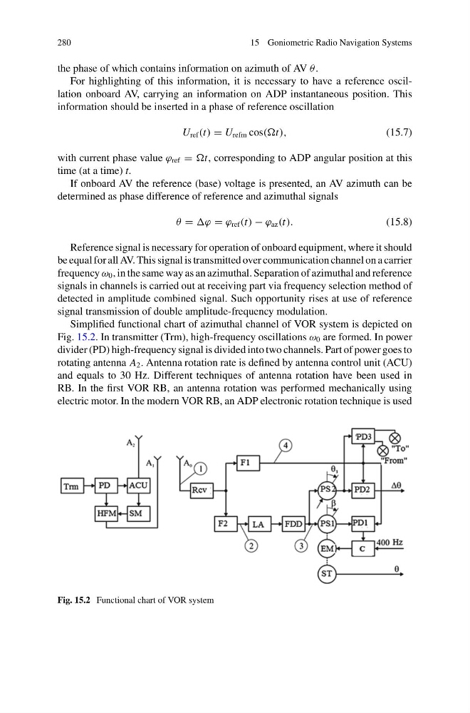
Simplified functional chart of azimuthal channel of VOR system is depicted on
Fig. 15.2. In transmitter (Trm), high-frequency oscillations ω 0 are formed. In power
divider (PD) high-frequency signal is divided into two channels. Part of power goes to
rotating antenna A 2 . Antenna rotation rate is defined by antenna control unit (ACU)
and equals to 30 Hz. Different techniques of antenna rotation have been used in
RB. In the first VOR RB, an antenna rotation was performed mechanically using
electric motor. In the modern VOR RB, an ADP electronic rotation technique is used
Fig. 15.2 Functional chart of VOR system
15 Goniometric Radio Navigation Systems
the phase of which contains information on azimuth of AV θ .
For highlighting of this information, it is necessary to have a reference oscillation onboard AV, carrying an information on ADP instantaneous position. This
information should be inserted in a phase of reference oscillation
U ref (t) = U refm cos(t),
(15.7)
with current phase value ϕ ref = t, corresponding to ADP angular position at this
time (at a time) t.
If onboard AV the reference (base) voltage is presented, an AV azimuth can be
determined as phase difference of reference and azimuthal signals
θ = ϕ = ϕ ref (t) − ϕ az (t).
(15.8)
Reference signal is necessary for operation of onboard equipment, where it should
be equal for all AV. This signal is transmitted over communication channel on a carrier
frequency ω 0 , in the same way as an azimuthal. Separation of azimuthal and reference
signals in channels is carried out at receiving part via frequency selection method of
detected in amplitude combined signal. Such opportunity rises at use of reference
signal transmission of double amplitude-frequency modulation.
Simplified functional chart of azimuthal channel of VOR system is depicted on
Fig. 15.2. In transmitter (Trm), high-frequency oscillations ω 0 are formed. In power
divider (PD) high-frequency signal is divided into two channels. Part of power goes to
rotating antenna A 2 . Antenna rotation rate is defined by antenna control unit (ACU)
and equals to 30 Hz. Different techniques of antenna rotation have been used in
RB. In the first VOR RB, an antenna rotation was performed mechanically using
electric motor. In the modern VOR RB, an ADP electronic rotation technique is used
Fig. 15.2 Functional chart of VOR system