

15.1 Radio Beacon Goniometric Radio Navigation Systems
279
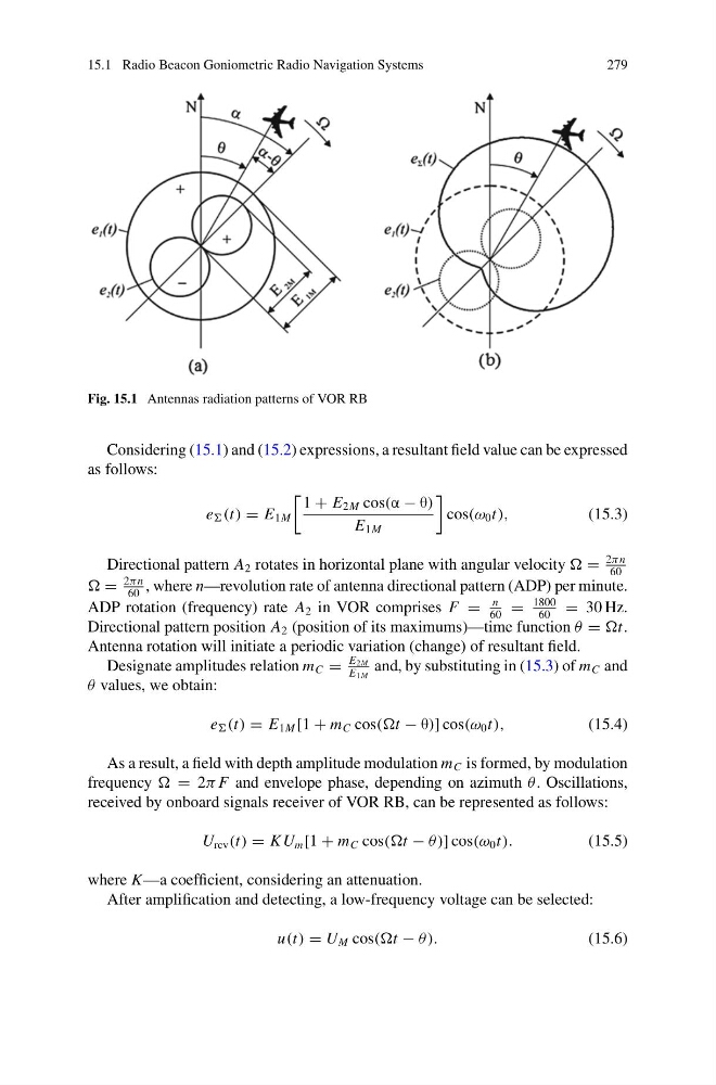
Fig. 15.1 Antennas radiation patterns of VOR RB
Considering (15.1) and (15.2) expressions, a resultant field value can be expressed
as follows:
e (t) = E 1M
1 + E 2M cos(α − θ)
E 1M
cos(ω 0 t),
(15.3)
Directional pattern A 2 rotates in horizontal plane with angular velocity =
2πn
60
=
2πn
60
, where n—revolution rate of antenna directional pattern (ADP) per minute.
ADP rotation (frequency) rate A 2 in VOR comprises F =
n
60
=
1800
60
= 30 Hz.
Directional pattern position A 2 (position of its maximums)—time function θ = t.
Antenna rotation will initiate a periodic variation (change) of resultant field.
Designate amplitudes relation m C =
E 2M
E 1M
and, by substituting in (15.3) of m C and
θ values, we obtain:
e (t) = E 1M [1 + m C cos(t − θ)] cos(ω 0 t),
(15.4)
As a result, a field with depth amplitude modulation m C is formed, by modulation
frequency = 2π F and envelope phase, depending on azimuth θ . Oscillations,
received by onboard signals receiver of VOR RB, can be represented as follows:
U rcv (t) = K U m [1 + m C cos(t − θ )] cos(ω 0 t).
(15.5)
where K—a coefficient, considering an attenuation.
After amplification and detecting, a low-frequency voltage can be selected:
u(t) = U M cos(t − θ ).
(15.6)
279
Fig. 15.1 Antennas radiation patterns of VOR RB
Considering (15.1) and (15.2) expressions, a resultant field value can be expressed
as follows:
e (t) = E 1M
1 + E 2M cos(α − θ)
E 1M
cos(ω 0 t),
(15.3)
Directional pattern A 2 rotates in horizontal plane with angular velocity =
2πn
60
=
2πn
60
, where n—revolution rate of antenna directional pattern (ADP) per minute.
ADP rotation (frequency) rate A 2 in VOR comprises F =
n
60
=
1800
60
= 30 Hz.
Directional pattern position A 2 (position of its maximums)—time function θ = t.
Antenna rotation will initiate a periodic variation (change) of resultant field.
Designate amplitudes relation m C =
E 2M
E 1M
and, by substituting in (15.3) of m C and
θ values, we obtain:
e (t) = E 1M [1 + m C cos(t − θ)] cos(ω 0 t),
(15.4)
As a result, a field with depth amplitude modulation m C is formed, by modulation
frequency = 2π F and envelope phase, depending on azimuth θ . Oscillations,
received by onboard signals receiver of VOR RB, can be represented as follows:
U rcv (t) = K U m [1 + m C cos(t − θ )] cos(ω 0 t).
(15.5)
where K—a coefficient, considering an attenuation.
After amplification and detecting, a low-frequency voltage can be selected:
u(t) = U M cos(t − θ ).
(15.6)