

244
14 Pseudo-Ranging Radio Navigation Systems
d(t) =
(x rb (t) − x ob (t))
2
+ (y rb (t) − y ob (t))
2
+ νδτ,
(14.1)
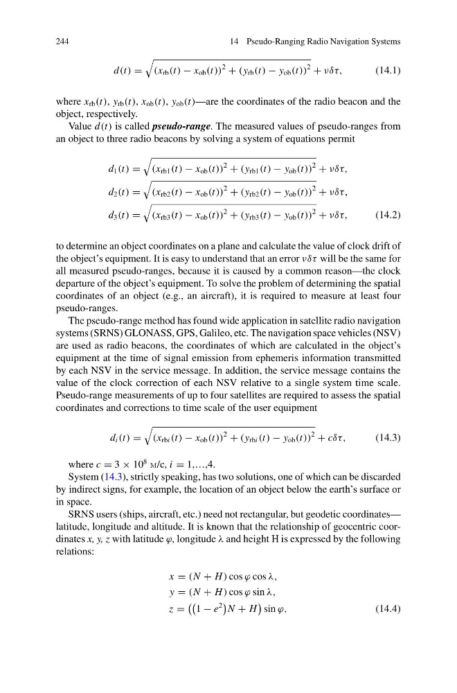
where x rb (t), y rb (t), x ob (t), y ob (t)—are the coordinates of the radio beacon and the
object, respectively.
Value d(t) is called pseudo-range. The measured values of pseudo-ranges from
an object to three radio beacons by solving a system of equations permit
d 1 (t) =
(x rb1 (t) − x ob (t))
2
+ (y rb1 (t) − y ob (t))
2
+ νδτ,
d 2 (t) =
(x rb2 (t) − x ob (t))
2
+ (y rb2 (t) − y ob (t))
2
+ νδτ,
d 3 (t) =
(x rb3 (t) − x ob (t))
2
+ (y rb3 (t) − y ob (t))
2
+ νδτ,
(14.2)
to determine an object coordinates on a plane and calculate the value of clock drift of
the object’s equipment. It is easy to understand that an error νδτ will be the same for
all measured pseudo-ranges, because it is caused by a common reason—the clock
departure of the object’s equipment. To solve the problem of determining the spatial
coordinates of an object (e.g., an aircraft), it is required to measure at least four
pseudo-ranges.
The pseudo-range method has found wide application in satellite radio navigation
systems (SRNS) GLONASS, GPS, Galileo, etc. The navigation space vehicles (NSV)
are used as radio beacons, the coordinates of which are calculated in the object’s
equipment at the time of signal emission from ephemeris information transmitted
by each NSV in the service message. In addition, the service message contains the
value of the clock correction of each NSV relative to a single system time scale.
Pseudo-range measurements of up to four satellites are required to assess the spatial
coordinates and corrections to time scale of the user equipment
d i (t) =
(x rbi (t) − x ob (t))
2
+ (y rbi (t) − y ob (t))
2
+ cδτ,
(14.3)
where c = 3 × 10
8
m/c, i = 1,…,4.
System (14.3), strictly speaking, has two solutions, one of which can be discarded
by indirect signs, for example, the location of an object below the earth’s surface or
in space.
SRNS users (ships, aircraft, etc.) need not rectangular, but geodetic coordinates—
latitude, longitude and altitude. It is known that the relationship of geocentric coordinates x, y, z with latitude ϕ, longitude λ and height H is expressed by the following
relations:
x = (N + H ) cos ϕ cos λ,
y = (N + H ) cos ϕ sin λ,
z =
1 − e
2
N + H
sin ϕ,
(14.4)
14 Pseudo-Ranging Radio Navigation Systems
d(t) =
(x rb (t) − x ob (t))
2
+ (y rb (t) − y ob (t))
2
+ νδτ,
(14.1)
where x rb (t), y rb (t), x ob (t), y ob (t)—are the coordinates of the radio beacon and the
object, respectively.
Value d(t) is called pseudo-range. The measured values of pseudo-ranges from
an object to three radio beacons by solving a system of equations permit
d 1 (t) =
(x rb1 (t) − x ob (t))
2
+ (y rb1 (t) − y ob (t))
2
+ νδτ,
d 2 (t) =
(x rb2 (t) − x ob (t))
2
+ (y rb2 (t) − y ob (t))
2
+ νδτ,
d 3 (t) =
(x rb3 (t) − x ob (t))
2
+ (y rb3 (t) − y ob (t))
2
+ νδτ,
(14.2)
to determine an object coordinates on a plane and calculate the value of clock drift of
the object’s equipment. It is easy to understand that an error νδτ will be the same for
all measured pseudo-ranges, because it is caused by a common reason—the clock
departure of the object’s equipment. To solve the problem of determining the spatial
coordinates of an object (e.g., an aircraft), it is required to measure at least four
pseudo-ranges.
The pseudo-range method has found wide application in satellite radio navigation
systems (SRNS) GLONASS, GPS, Galileo, etc. The navigation space vehicles (NSV)
are used as radio beacons, the coordinates of which are calculated in the object’s
equipment at the time of signal emission from ephemeris information transmitted
by each NSV in the service message. In addition, the service message contains the
value of the clock correction of each NSV relative to a single system time scale.
Pseudo-range measurements of up to four satellites are required to assess the spatial
coordinates and corrections to time scale of the user equipment
d i (t) =
(x rbi (t) − x ob (t))
2
+ (y rbi (t) − y ob (t))
2
+ cδτ,
(14.3)
where c = 3 × 10
8
m/c, i = 1,…,4.
System (14.3), strictly speaking, has two solutions, one of which can be discarded
by indirect signs, for example, the location of an object below the earth’s surface or
in space.
SRNS users (ships, aircraft, etc.) need not rectangular, but geodetic coordinates—
latitude, longitude and altitude. It is known that the relationship of geocentric coordinates x, y, z with latitude ϕ, longitude λ and height H is expressed by the following
relations:
x = (N + H ) cos ϕ cos λ,
y = (N + H ) cos ϕ sin λ,
z =
1 − e
2
N + H
sin ϕ,
(14.4)