

222
12 Radar Systems of Maritime Transport
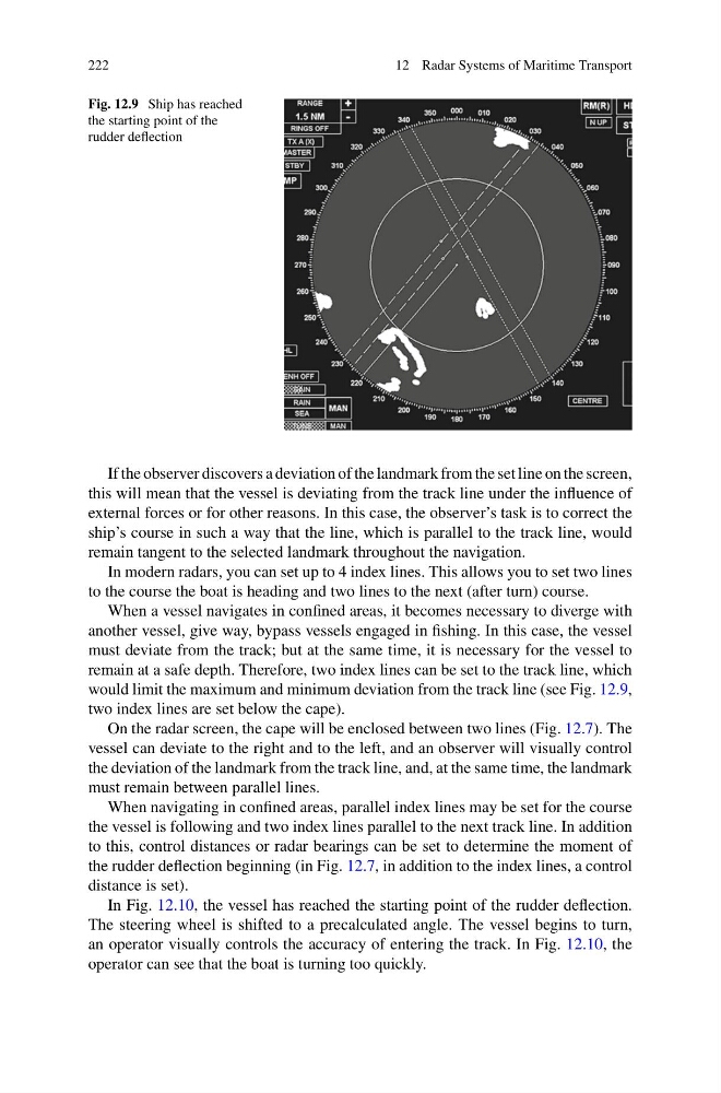
Fig. 12.9 Ship has reached
the starting point of the
rudder deflection
If the observer discovers a deviation of the landmark from the set line on the screen,
this will mean that the vessel is deviating from the track line under the influence of
external forces or for other reasons. In this case, the observer’s task is to correct the
ship’s course in such a way that the line, which is parallel to the track line, would
remain tangent to the selected landmark throughout the navigation.
In modern radars, you can set up to 4 index lines. This allows you to set two lines
to the course the boat is heading and two lines to the next (after turn) course.
When a vessel navigates in confined areas, it becomes necessary to diverge with
another vessel, give way, bypass vessels engaged in fishing. In this case, the vessel
must deviate from the track; but at the same time, it is necessary for the vessel to
remain at a safe depth. Therefore, two index lines can be set to the track line, which
would limit the maximum and minimum deviation from the track line (see Fig. 12.9,
two index lines are set below the cape).
On the radar screen, the cape will be enclosed between two lines (Fig. 12.7). The
vessel can deviate to the right and to the left, and an observer will visually control
the deviation of the landmark from the track line, and, at the same time, the landmark
must remain between parallel lines.
When navigating in confined areas, parallel index lines may be set for the course
the vessel is following and two index lines parallel to the next track line. In addition
to this, control distances or radar bearings can be set to determine the moment of
the rudder deflection beginning (in Fig. 12.7, in addition to the index lines, a control
distance is set).
In Fig. 12.10, the vessel has reached the starting point of the rudder deflection.
The steering wheel is shifted to a precalculated angle. The vessel begins to turn,
an operator visually controls the accuracy of entering the track. In Fig. 12.10, the
operator can see that the boat is turning too quickly.
12 Radar Systems of Maritime Transport
Fig. 12.9 Ship has reached
the starting point of the
rudder deflection
If the observer discovers a deviation of the landmark from the set line on the screen,
this will mean that the vessel is deviating from the track line under the influence of
external forces or for other reasons. In this case, the observer’s task is to correct the
ship’s course in such a way that the line, which is parallel to the track line, would
remain tangent to the selected landmark throughout the navigation.
In modern radars, you can set up to 4 index lines. This allows you to set two lines
to the course the boat is heading and two lines to the next (after turn) course.
When a vessel navigates in confined areas, it becomes necessary to diverge with
another vessel, give way, bypass vessels engaged in fishing. In this case, the vessel
must deviate from the track; but at the same time, it is necessary for the vessel to
remain at a safe depth. Therefore, two index lines can be set to the track line, which
would limit the maximum and minimum deviation from the track line (see Fig. 12.9,
two index lines are set below the cape).
On the radar screen, the cape will be enclosed between two lines (Fig. 12.7). The
vessel can deviate to the right and to the left, and an observer will visually control
the deviation of the landmark from the track line, and, at the same time, the landmark
must remain between parallel lines.
When navigating in confined areas, parallel index lines may be set for the course
the vessel is following and two index lines parallel to the next track line. In addition
to this, control distances or radar bearings can be set to determine the moment of
the rudder deflection beginning (in Fig. 12.7, in addition to the index lines, a control
distance is set).
In Fig. 12.10, the vessel has reached the starting point of the rudder deflection.
The steering wheel is shifted to a precalculated angle. The vessel begins to turn,
an operator visually controls the accuracy of entering the track. In Fig. 12.10, the
operator can see that the boat is turning too quickly.