

11 Radar Systems of Air Transport
197
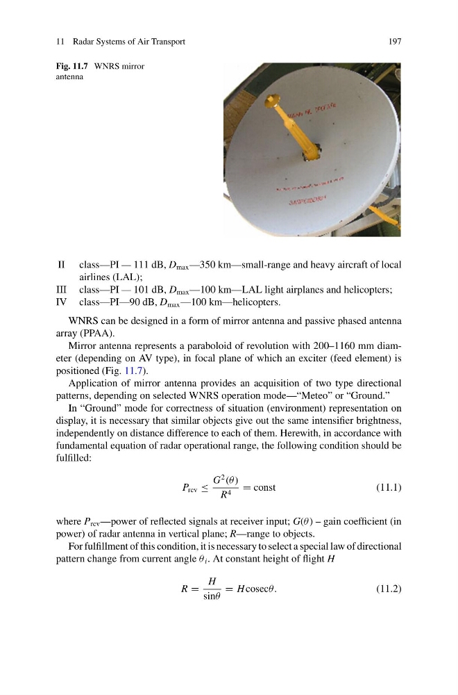
Fig. 11.7 WNRS mirror
antenna
II class—PI — 111 dB, D max —350 km—small-range and heavy aircraft of local
airlines (LAL);
III class—PI — 101 dB, D max —100 km—LAL light airplanes and helicopters;
IV class—PI—90 dB, D max —100 km—helicopters.
WNRS can be designed in a form of mirror antenna and passive phased antenna
array (PPAA).
Mirror antenna represents a paraboloid of revolution with 200–1160 mm diameter (depending on AV type), in focal plane of which an exciter (feed element) is
positioned (Fig. 11.7).
Application of mirror antenna provides an acquisition of two type directional
patterns, depending on selected WNRS operation mode—“Meteo” or “Ground.”
In “Ground” mode for correctness of situation (environment) representation on
display, it is necessary that similar objects give out the same intensifier brightness,
independently on distance difference to each of them. Herewith, in accordance with
fundamental equation of radar operational range, the following condition should be
fulfilled:
P rcv ≤
G
2
(θ )
R 4 = const
(11.1)
where P rcv —power of reflected signals at receiver input; G(θ ) – gain coefficient (in
power) of radar antenna in vertical plane; R—range to objects.
For fulfillment of this condition, it is necessary to select a special law of directional
pattern change from current angle θ i . At constant height of flight H
R =
H
sinθ
= H cosecθ.
(11.2)
197
Fig. 11.7 WNRS mirror
antenna
II class—PI — 111 dB, D max —350 km—small-range and heavy aircraft of local
airlines (LAL);
III class—PI — 101 dB, D max —100 km—LAL light airplanes and helicopters;
IV class—PI—90 dB, D max —100 km—helicopters.
WNRS can be designed in a form of mirror antenna and passive phased antenna
array (PPAA).
Mirror antenna represents a paraboloid of revolution with 200–1160 mm diameter (depending on AV type), in focal plane of which an exciter (feed element) is
positioned (Fig. 11.7).
Application of mirror antenna provides an acquisition of two type directional
patterns, depending on selected WNRS operation mode—“Meteo” or “Ground.”
In “Ground” mode for correctness of situation (environment) representation on
display, it is necessary that similar objects give out the same intensifier brightness,
independently on distance difference to each of them. Herewith, in accordance with
fundamental equation of radar operational range, the following condition should be
fulfilled:
P rcv ≤
G
2
(θ )
R 4 = const
(11.1)
where P rcv —power of reflected signals at receiver input; G(θ ) – gain coefficient (in
power) of radar antenna in vertical plane; R—range to objects.
For fulfillment of this condition, it is necessary to select a special law of directional
pattern change from current angle θ i . At constant height of flight H
R =
H
sinθ
= H cosecθ.
(11.2)