

194
11 Radar Systems of Air Transport
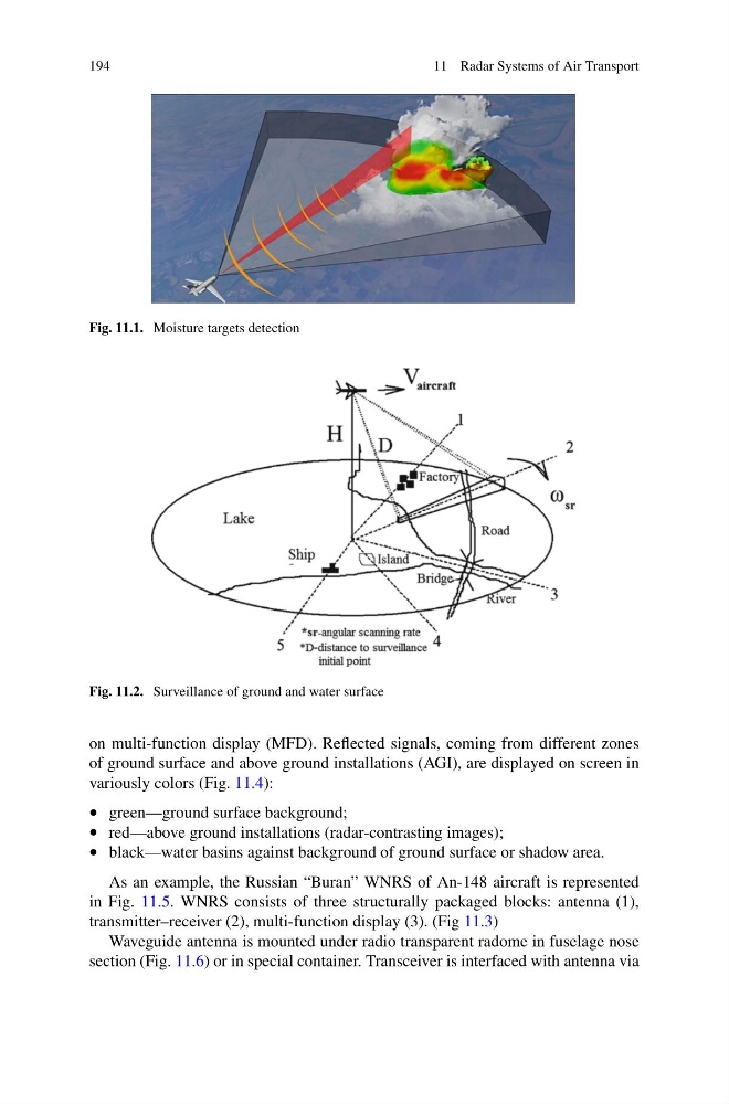
Fig. 11.1. Moisture targets detection
Fig. 11.2. Surveillance of ground and water surface
on multi-function display (MFD). Reflected signals, coming from different zones
of ground surface and above ground installations (AGI), are displayed on screen in
variously colors (Fig. 11.4):
• green—ground surface background;
• red—above ground installations (radar-contrasting images);
• black—water basins against background of ground surface or shadow area.
As an example, the Russian “Buran” WNRS of An-148 aircraft is represented
in Fig. 11.5. WNRS consists of three structurally packaged blocks: antenna (1),
transmitter–receiver (2), multi-function display (3). (Fig 11.3)
Waveguide antenna is mounted under radio transparent radome in fuselage nose
section (Fig. 11.6) or in special container. Transceiver is interfaced with antenna via
11 Radar Systems of Air Transport
Fig. 11.1. Moisture targets detection
Fig. 11.2. Surveillance of ground and water surface
on multi-function display (MFD). Reflected signals, coming from different zones
of ground surface and above ground installations (AGI), are displayed on screen in
variously colors (Fig. 11.4):
• green—ground surface background;
• red—above ground installations (radar-contrasting images);
• black—water basins against background of ground surface or shadow area.
As an example, the Russian “Buran” WNRS of An-148 aircraft is represented
in Fig. 11.5. WNRS consists of three structurally packaged blocks: antenna (1),
transmitter–receiver (2), multi-function display (3). (Fig 11.3)
Waveguide antenna is mounted under radio transparent radome in fuselage nose
section (Fig. 11.6) or in special container. Transceiver is interfaced with antenna via