

176
9 Compensation of Signals from Stationary Objects
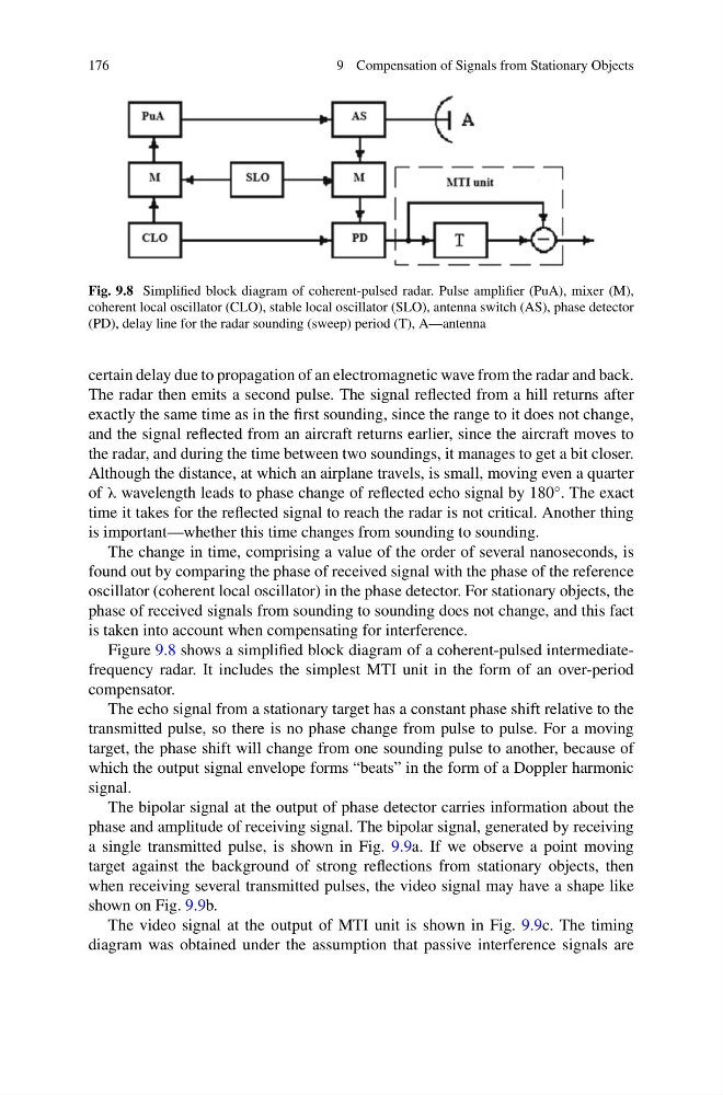
Fig. 9.8 Simplified block diagram of coherent-pulsed radar. Pulse amplifier (PuA), mixer (M),
coherent local oscillator (CLO), stable local oscillator (SLO), antenna switch (AS), phase detector
(PD), delay line for the radar sounding (sweep) period (T), A—antenna
certain delay due to propagation of an electromagnetic wave from the radar and back.
The radar then emits a second pulse. The signal reflected from a hill returns after
exactly the same time as in the first sounding, since the range to it does not change,
and the signal reflected from an aircraft returns earlier, since the aircraft moves to
the radar, and during the time between two soundings, it manages to get a bit closer.
Although the distance, at which an airplane travels, is small, moving even a quarter
of λ wavelength leads to phase change of reflected echo signal by 180°. The exact
time it takes for the reflected signal to reach the radar is not critical. Another thing
is important—whether this time changes from sounding to sounding.
The change in time, comprising a value of the order of several nanoseconds, is
found out by comparing the phase of received signal with the phase of the reference
oscillator (coherent local oscillator) in the phase detector. For stationary objects, the
phase of received signals from sounding to sounding does not change, and this fact
is taken into account when compensating for interference.
Figure 9.8 shows a simplified block diagram of a coherent-pulsed intermediatefrequency radar. It includes the simplest MTI unit in the form of an over-period
compensator.
The echo signal from a stationary target has a constant phase shift relative to the
transmitted pulse, so there is no phase change from pulse to pulse. For a moving
target, the phase shift will change from one sounding pulse to another, because of
which the output signal envelope forms “beats” in the form of a Doppler harmonic
signal.
The bipolar signal at the output of phase detector carries information about the
phase and amplitude of receiving signal. The bipolar signal, generated by receiving
a single transmitted pulse, is shown in Fig. 9.9a. If we observe a point moving
target against the background of strong reflections from stationary objects, then
when receiving several transmitted pulses, the video signal may have a shape like
shown on Fig. 9.9b.
The video signal at the output of MTI unit is shown in Fig. 9.9c. The timing
diagram was obtained under the assumption that passive interference signals are
9 Compensation of Signals from Stationary Objects
Fig. 9.8 Simplified block diagram of coherent-pulsed radar. Pulse amplifier (PuA), mixer (M),
coherent local oscillator (CLO), stable local oscillator (SLO), antenna switch (AS), phase detector
(PD), delay line for the radar sounding (sweep) period (T), A—antenna
certain delay due to propagation of an electromagnetic wave from the radar and back.
The radar then emits a second pulse. The signal reflected from a hill returns after
exactly the same time as in the first sounding, since the range to it does not change,
and the signal reflected from an aircraft returns earlier, since the aircraft moves to
the radar, and during the time between two soundings, it manages to get a bit closer.
Although the distance, at which an airplane travels, is small, moving even a quarter
of λ wavelength leads to phase change of reflected echo signal by 180°. The exact
time it takes for the reflected signal to reach the radar is not critical. Another thing
is important—whether this time changes from sounding to sounding.
The change in time, comprising a value of the order of several nanoseconds, is
found out by comparing the phase of received signal with the phase of the reference
oscillator (coherent local oscillator) in the phase detector. For stationary objects, the
phase of received signals from sounding to sounding does not change, and this fact
is taken into account when compensating for interference.
Figure 9.8 shows a simplified block diagram of a coherent-pulsed intermediatefrequency radar. It includes the simplest MTI unit in the form of an over-period
compensator.
The echo signal from a stationary target has a constant phase shift relative to the
transmitted pulse, so there is no phase change from pulse to pulse. For a moving
target, the phase shift will change from one sounding pulse to another, because of
which the output signal envelope forms “beats” in the form of a Doppler harmonic
signal.
The bipolar signal at the output of phase detector carries information about the
phase and amplitude of receiving signal. The bipolar signal, generated by receiving
a single transmitted pulse, is shown in Fig. 9.9a. If we observe a point moving
target against the background of strong reflections from stationary objects, then
when receiving several transmitted pulses, the video signal may have a shape like
shown on Fig. 9.9b.
The video signal at the output of MTI unit is shown in Fig. 9.9c. The timing
diagram was obtained under the assumption that passive interference signals are