

174
9 Compensation of Signals from Stationary Objects
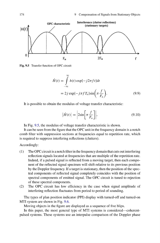
Fig. 9.5 Transfer function of OPC circuit
˙
H (t) =
∞
−∞
h(t) exp{− j2π f t}dt
= 2 j exp{− jπ f T n }sin
π
f
F n
,
(9.9)
It is possible to obtain the modulus of voltage transfer characteristic:
˙
H (t)
=
2sin
π
f
F n
,
(9.10)
In Fig. 9.5, the modulus of voltage transfer characteristic is shown.
It can be seen from the figure that the OPC unit in the frequency domain is a notch
comb filter with suppression sections at frequencies equal to repetition rate, which
is required to suppress interfering reflections (clutters).
Accordingly:
(1) The OPC circuit is a notch filter in the frequency domain that cuts out interfering
reflection signals located at frequencies that are multiple of the repetition rate.
Indeed, if a pulsed signal is reflected from a moving target, then each component of the reflected signal spectrum will shift relative to its previous position
by the Doppler frequency. If a target is stationary, then the position of the spectral components of reflected signal completely coincides with the position of
spectral components of emitted signal. The OPC circuit is tuned to rejection
of these spectral components.
(2) The OPC circuit has low efficiency in the case when signal amplitude of
interfering reflection fluctuates from period to period of sounding.
The types of plan position indicator (PPI) display with turned-off and turned-on
MTI system are shown in Fig. 9.6.
Moving objects in the figure are displayed as a sequence of five blips.
In this paper, the most general type of MTI systems is considered—coherentpulsed systems. These systems use an interpulse comparison of the Doppler phase
9 Compensation of Signals from Stationary Objects
Fig. 9.5 Transfer function of OPC circuit
˙
H (t) =
∞
−∞
h(t) exp{− j2π f t}dt
= 2 j exp{− jπ f T n }sin
π
f
F n
,
(9.9)
It is possible to obtain the modulus of voltage transfer characteristic:
˙
H (t)
=
2sin
π
f
F n
,
(9.10)
In Fig. 9.5, the modulus of voltage transfer characteristic is shown.
It can be seen from the figure that the OPC unit in the frequency domain is a notch
comb filter with suppression sections at frequencies equal to repetition rate, which
is required to suppress interfering reflections (clutters).
Accordingly:
(1) The OPC circuit is a notch filter in the frequency domain that cuts out interfering
reflection signals located at frequencies that are multiple of the repetition rate.
Indeed, if a pulsed signal is reflected from a moving target, then each component of the reflected signal spectrum will shift relative to its previous position
by the Doppler frequency. If a target is stationary, then the position of the spectral components of reflected signal completely coincides with the position of
spectral components of emitted signal. The OPC circuit is tuned to rejection
of these spectral components.
(2) The OPC circuit has low efficiency in the case when signal amplitude of
interfering reflection fluctuates from period to period of sounding.
The types of plan position indicator (PPI) display with turned-off and turned-on
MTI system are shown in Fig. 9.6.
Moving objects in the figure are displayed as a sequence of five blips.
In this paper, the most general type of MTI systems is considered—coherentpulsed systems. These systems use an interpulse comparison of the Doppler phase