

172
9 Compensation of Signals from Stationary Objects
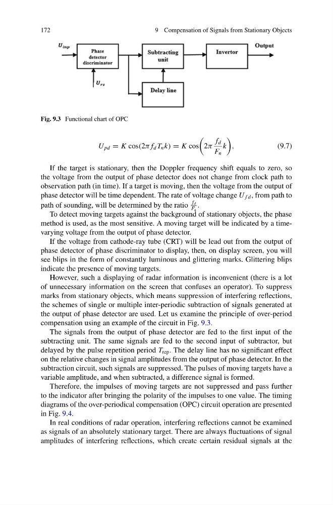
Fig. 9.3 Functional chart of OPC
U pd = K cos(2π f d T n k) = K cos
2π
f d
F n
k
,
(9.7)
If the target is stationary, then the Doppler frequency shift equals to zero, so
the voltage from the output of phase detector does not change from clock path to
observation path (in time). If a target is moving, then the voltage from the output of
phase detector will be time dependent. The rate of voltage change U f d , from path to
path of sounding, will be determined by the ratio
f d
F n
.
To detect moving targets against the background of stationary objects, the phase
method is used, as the most sensitive. A moving target will be indicated by a timevarying voltage from the output of phase detector.
If the voltage from cathode-ray tube (CRT) will be lead out from the output of
phase detector of phase discriminator to display, then, on display screen, you will
see blips in the form of constantly luminous and glittering marks. Glittering blips
indicate the presence of moving targets.
However, such a displaying of radar information is inconvenient (there is a lot
of unnecessary information on the screen that confuses an operator). To suppress
marks from stationary objects, which means suppression of interfering reflections,
the schemes of single or multiple inter-periodic subtraction of signals generated at
the output of phase detector are used. Let us examine the principle of over-period
compensation using an example of the circuit in Fig. 9.3.
The signals from the output of phase detector are fed to the first input of the
subtracting unit. The same signals are fed to the second input of subtractor, but
delayed by the pulse repetition period T rep . The delay line has no significant effect
on the relative changes in signal amplitudes from the output of phase detector. In the
subtraction circuit, such signals are suppressed. The pulses of moving targets have a
variable amplitude, and when subtracted, a difference signal is formed.
Therefore, the impulses of moving targets are not suppressed and pass further
to the indicator after bringing the polarity of the impulses to one value. The timing
diagrams of the over-periodical compensation (OPC) circuit operation are presented
in Fig. 9.4.
In real conditions of radar operation, interfering reflections cannot be examined
as signals of an absolutely stationary target. There are always fluctuations of signal
amplitudes of interfering reflections, which create certain residual signals at the
9 Compensation of Signals from Stationary Objects
Fig. 9.3 Functional chart of OPC
U pd = K cos(2π f d T n k) = K cos
2π
f d
F n
k
,
(9.7)
If the target is stationary, then the Doppler frequency shift equals to zero, so
the voltage from the output of phase detector does not change from clock path to
observation path (in time). If a target is moving, then the voltage from the output of
phase detector will be time dependent. The rate of voltage change U f d , from path to
path of sounding, will be determined by the ratio
f d
F n
.
To detect moving targets against the background of stationary objects, the phase
method is used, as the most sensitive. A moving target will be indicated by a timevarying voltage from the output of phase detector.
If the voltage from cathode-ray tube (CRT) will be lead out from the output of
phase detector of phase discriminator to display, then, on display screen, you will
see blips in the form of constantly luminous and glittering marks. Glittering blips
indicate the presence of moving targets.
However, such a displaying of radar information is inconvenient (there is a lot
of unnecessary information on the screen that confuses an operator). To suppress
marks from stationary objects, which means suppression of interfering reflections,
the schemes of single or multiple inter-periodic subtraction of signals generated at
the output of phase detector are used. Let us examine the principle of over-period
compensation using an example of the circuit in Fig. 9.3.
The signals from the output of phase detector are fed to the first input of the
subtracting unit. The same signals are fed to the second input of subtractor, but
delayed by the pulse repetition period T rep . The delay line has no significant effect
on the relative changes in signal amplitudes from the output of phase detector. In the
subtraction circuit, such signals are suppressed. The pulses of moving targets have a
variable amplitude, and when subtracted, a difference signal is formed.
Therefore, the impulses of moving targets are not suppressed and pass further
to the indicator after bringing the polarity of the impulses to one value. The timing
diagrams of the over-periodical compensation (OPC) circuit operation are presented
in Fig. 9.4.
In real conditions of radar operation, interfering reflections cannot be examined
as signals of an absolutely stationary target. There are always fluctuations of signal
amplitudes of interfering reflections, which create certain residual signals at the