

9 Compensation of Signals from Stationary Objects
171
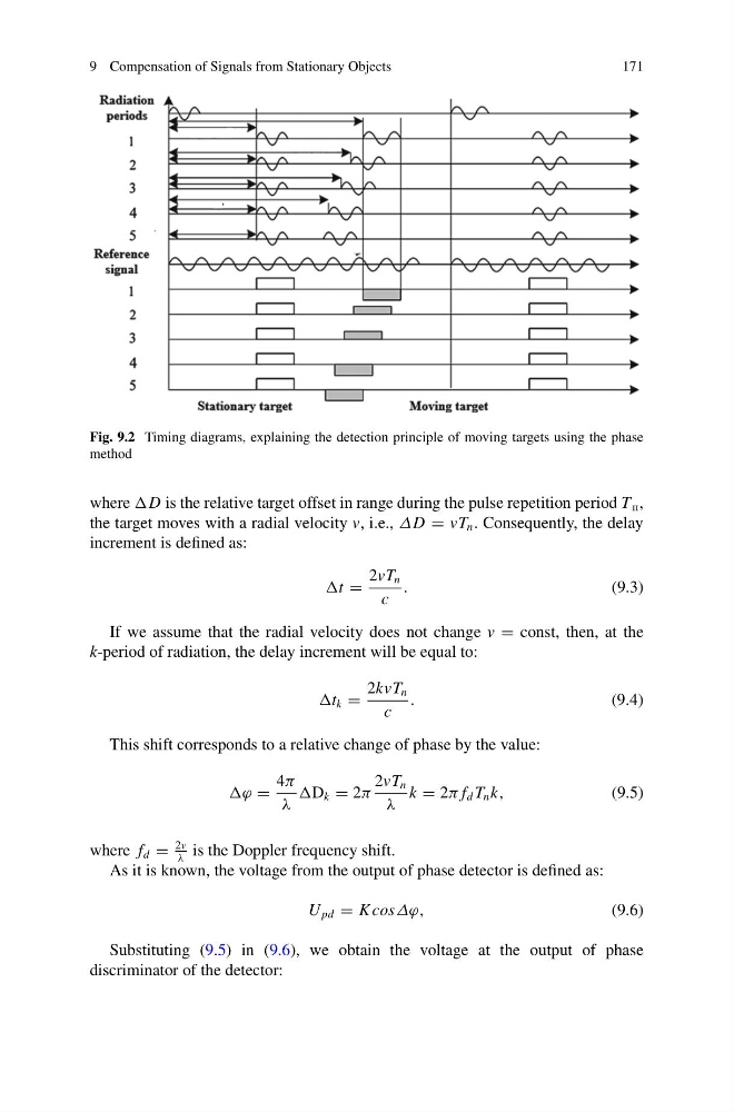
Fig. 9.2 Timing diagrams, explaining the detection principle of moving targets using the phase
method
where D is the relative target offset in range during the pulse repetition period T p ,
the target moves with a radial velocity v, i.e., ΔD = vT n . Consequently, the delay
increment is defined as:
t =
2vT n
c
.
(9.3)
If we assume that the radial velocity does not change v = const, then, at the
k-period of radiation, the delay increment will be equal to:
t k =
2kvT n
c
.
(9.4)
This shift corresponds to a relative change of phase by the value:
ϕ =
4π
λ
D k = 2π
2vT n
λ
k = 2π f d T n k,
(9.5)
where f d =
2v
λ
is the Doppler frequency shift.
As it is known, the voltage from the output of phase detector is defined as:
U pd = K cosΔϕ,
(9.6)
Substituting (9.5) in (9.6), we obtain the voltage at the output of phase
discriminator of the detector:
171
Fig. 9.2 Timing diagrams, explaining the detection principle of moving targets using the phase
method
where D is the relative target offset in range during the pulse repetition period T p ,
the target moves with a radial velocity v, i.e., ΔD = vT n . Consequently, the delay
increment is defined as:
t =
2vT n
c
.
(9.3)
If we assume that the radial velocity does not change v = const, then, at the
k-period of radiation, the delay increment will be equal to:
t k =
2kvT n
c
.
(9.4)
This shift corresponds to a relative change of phase by the value:
ϕ =
4π
λ
D k = 2π
2vT n
λ
k = 2π f d T n k,
(9.5)
where f d =
2v
λ
is the Doppler frequency shift.
As it is known, the voltage from the output of phase detector is defined as:
U pd = K cosΔϕ,
(9.6)
Substituting (9.5) in (9.6), we obtain the voltage at the output of phase
discriminator of the detector: