

162
8 Coherent Radar Systems
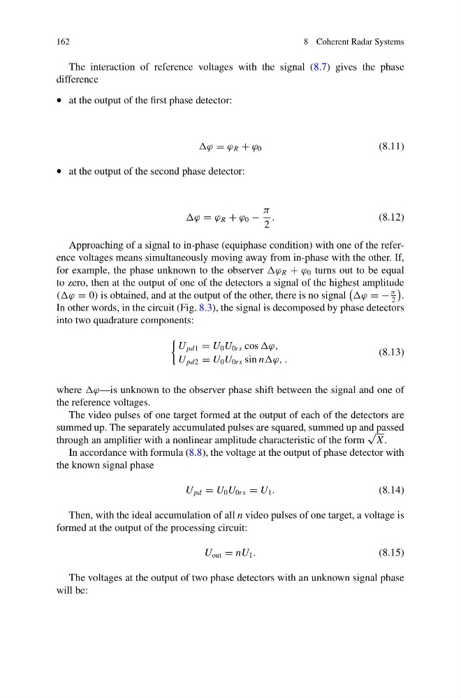
The interaction of reference voltages with the signal (8.7) gives the phase
difference
• at the output of the first phase detector:
ϕ = ϕ R + ϕ 0
(8.11)
• at the output of the second phase detector:
ϕ = ϕ R + ϕ 0 −
π
2
.
(8.12)
Approaching of a signal to in-phase (equiphase condition) with one of the reference voltages means simultaneously moving away from in-phase with the other. If,
for example, the phase unknown to the observer ϕ R + ϕ 0 turns out to be equal
to zero, then at the output of one of the detectors a signal of the highest amplitude
((ϕ = 0) is obtained, and at the output of the other, there is no signal
ϕ = −
π
2
.
In other words, in the circuit (Fig. 8.3), the signal is decomposed by phase detectors
into two quadrature components:
U pd1 = U 0 U 0rs cos
U pd2 = U 0 U 0rs sin nϕ, .
(8.13)
where ϕ—is unknown to the observer phase shift between the signal and one of
the reference voltages.
The video pulses of one target formed at the output of each of the detectors are
summed up. The separately accumulated pulses are squared, summed up and passed
through an amplifier with a nonlinear amplitude characteristic of the form
√
X .
In accordance with formula (8.8), the voltage at the output of phase detector with
the known signal phase
U pd = U 0 U 0rs = U 1 .
(8.14)
Then, with the ideal accumulation of all n video pulses of one target, a voltage is
formed at the output of the processing circuit:
U out = nU 1 .
(8.15)
The voltages at the output of two phase detectors with an unknown signal phase
will be:
8 Coherent Radar Systems
The interaction of reference voltages with the signal (8.7) gives the phase
difference
• at the output of the first phase detector:
ϕ = ϕ R + ϕ 0
(8.11)
• at the output of the second phase detector:
ϕ = ϕ R + ϕ 0 −
π
2
.
(8.12)
Approaching of a signal to in-phase (equiphase condition) with one of the reference voltages means simultaneously moving away from in-phase with the other. If,
for example, the phase unknown to the observer ϕ R + ϕ 0 turns out to be equal
to zero, then at the output of one of the detectors a signal of the highest amplitude
((ϕ = 0) is obtained, and at the output of the other, there is no signal
ϕ = −
π
2
.
In other words, in the circuit (Fig. 8.3), the signal is decomposed by phase detectors
into two quadrature components:
U pd1 = U 0 U 0rs cos
U pd2 = U 0 U 0rs sin nϕ, .
(8.13)
where ϕ—is unknown to the observer phase shift between the signal and one of
the reference voltages.
The video pulses of one target formed at the output of each of the detectors are
summed up. The separately accumulated pulses are squared, summed up and passed
through an amplifier with a nonlinear amplitude characteristic of the form
√
X .
In accordance with formula (8.8), the voltage at the output of phase detector with
the known signal phase
U pd = U 0 U 0rs = U 1 .
(8.14)
Then, with the ideal accumulation of all n video pulses of one target, a voltage is
formed at the output of the processing circuit:
U out = nU 1 .
(8.15)
The voltages at the output of two phase detectors with an unknown signal phase
will be: