

8 Coherent Radar Systems
159
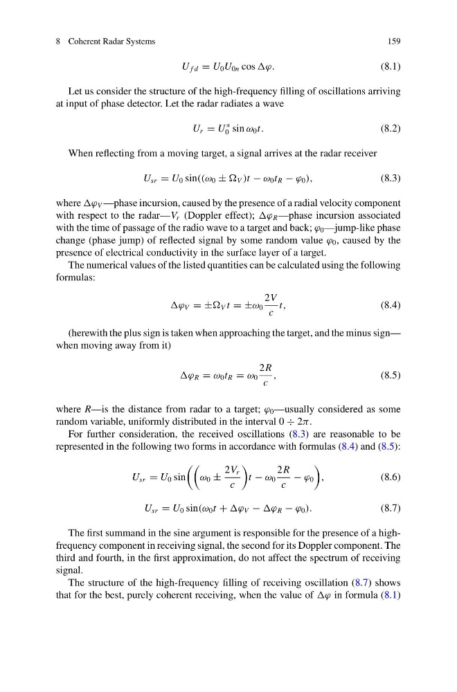
U f d = U 0 U 0n cos ϕ.
(8.1)
Let us consider the structure of the high-frequency filling of oscillations arriving
at input of phase detector. Let the radar radiates a wave
U r = U
∗
0 sin ω 0 t.
(8.2)
When reflecting from a moving target, a signal arrives at the radar receiver
U sr = U 0 sin((ω 0 ± V )t − ω 0 t R − ϕ 0 ),
(8.3)
where ϕ V —phase incursion, caused by the presence of a radial velocity component
with respect to the radar—V r (Doppler effect); ϕ R —phase incursion associated
with the time of passage of the radio wave to a target and back; ϕ 0 —jump-like phase
change (phase jump) of reflected signal by some random value ϕ 0 , caused by the
presence of electrical conductivity in the surface layer of a target.
The numerical values of the listed quantities can be calculated using the following
formulas:
ϕ V = ± V t = ±ω 0
2V
c
t,
(8.4)
(herewith the plus sign is taken when approaching the target, and the minus sign—
when moving away from it)
ϕ R = ω 0 t R = ω 0
2R
c
,
(8.5)
where R—is the distance from radar to a target; ϕ 0 —usually considered as some
random variable, uniformly distributed in the interval 0 ÷ 2π.
For further consideration, the received oscillations (8.3) are reasonable to be
represented in the following two forms in accordance with formulas (8.4) and (8.5):
U sr = U 0 sin
ω 0 ±
2V r
c
t − ω 0
2R
c
− ϕ 0
,
(8.6)
U sr = U 0 sin(ω 0 t + ϕ V − ϕ R − ϕ 0 ).
(8.7)
The first summand in the sine argument is responsible for the presence of a highfrequency component in receiving signal, the second for its Doppler component. The
third and fourth, in the first approximation, do not affect the spectrum of receiving
signal.
The structure of the high-frequency filling of receiving oscillation (8.7) shows
that for the best, purely coherent receiving, when the value of ϕ in formula (8.1)
159
U f d = U 0 U 0n cos ϕ.
(8.1)
Let us consider the structure of the high-frequency filling of oscillations arriving
at input of phase detector. Let the radar radiates a wave
U r = U
∗
0 sin ω 0 t.
(8.2)
When reflecting from a moving target, a signal arrives at the radar receiver
U sr = U 0 sin((ω 0 ± V )t − ω 0 t R − ϕ 0 ),
(8.3)
where ϕ V —phase incursion, caused by the presence of a radial velocity component
with respect to the radar—V r (Doppler effect); ϕ R —phase incursion associated
with the time of passage of the radio wave to a target and back; ϕ 0 —jump-like phase
change (phase jump) of reflected signal by some random value ϕ 0 , caused by the
presence of electrical conductivity in the surface layer of a target.
The numerical values of the listed quantities can be calculated using the following
formulas:
ϕ V = ± V t = ±ω 0
2V
c
t,
(8.4)
(herewith the plus sign is taken when approaching the target, and the minus sign—
when moving away from it)
ϕ R = ω 0 t R = ω 0
2R
c
,
(8.5)
where R—is the distance from radar to a target; ϕ 0 —usually considered as some
random variable, uniformly distributed in the interval 0 ÷ 2π.
For further consideration, the received oscillations (8.3) are reasonable to be
represented in the following two forms in accordance with formulas (8.4) and (8.5):
U sr = U 0 sin
ω 0 ±
2V r
c
t − ω 0
2R
c
− ϕ 0
,
(8.6)
U sr = U 0 sin(ω 0 t + ϕ V − ϕ R − ϕ 0 ).
(8.7)
The first summand in the sine argument is responsible for the presence of a highfrequency component in receiving signal, the second for its Doppler component. The
third and fourth, in the first approximation, do not affect the spectrum of receiving
signal.
The structure of the high-frequency filling of receiving oscillation (8.7) shows
that for the best, purely coherent receiving, when the value of ϕ in formula (8.1)