

158
8 Coherent Radar Systems
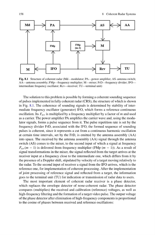
Fig. 8.1 Structure of coherent radar (Md—modulator; PA—power amplifier; AS–antenna switch;
AA—antenna assembly; FMp—frequency multiplier; M—mixer; FrD—frequency divider; IFO—
intermediate frequency oscillator; Rcv—receiver; TU—terminal unit)
The solution to this problem is possible by forming a coherent sounding sequence
of pulses implemented in fully coherent radar (CRS), the structure of which is shown
in Fig. 8.1. The coherence of sounding signals is determined by stability of intermediate frequency oscillator (generator) IFO, which forms a reference continuous
oscillation. Its F rcv is multiplied by a frequency multiplier by a factor of m and used
as a carrier. The power amplifier PA amplifies the carrier wave and, using the modulator signals, forms a pulse sequence from it. The pulse repetition rate is set by the
frequency divider FrD, associated with the IFO, the formed sequence of sounding
pulses is coherent, since it represents a cut from a continuous harmonic oscillation
at certain time intervals, set by the FrD, is emitted by the antenna assembly (AA)
into space. The received by the antenna assembly (AA) signal through the antenna
switch (AS) comes to the mixer, to the second input of which a signal at frequency
F rcv (m − 1) is delivered from frequency multiplier (FMp (m − 1)). As a result of
signal transformations in the mixer, the signal reflected from the target arrives at the
receiver input at a frequency close to the intermediate one, which differs from it by
the presence of a Doppler shift, stipulated by velocity of a target moving relatively to
the radar. To the second input of receiver a signal from the IFO arrives, which is the
reference one, for implementation of coherent processing. After the implementation
of joint processing of reference signal and reflected from a target, the information
goes to the terminal unit (TU) for indication or transmission of radar data to users.
The most important element of coherent radar receiver is a phase detector,
which replaces the envelope detector of none-coherent radar. The phase detector
compares (multiplies) the received and calibration (reference) voltages, as well as
high-frequency filtering and the formation of a target video pulse. The output voltage
of the phase detector after elimination of high-frequency components is proportional
to the cosine of phases between received and reference oscillations:
8 Coherent Radar Systems
Fig. 8.1 Structure of coherent radar (Md—modulator; PA—power amplifier; AS–antenna switch;
AA—antenna assembly; FMp—frequency multiplier; M—mixer; FrD—frequency divider; IFO—
intermediate frequency oscillator; Rcv—receiver; TU—terminal unit)
The solution to this problem is possible by forming a coherent sounding sequence
of pulses implemented in fully coherent radar (CRS), the structure of which is shown
in Fig. 8.1. The coherence of sounding signals is determined by stability of intermediate frequency oscillator (generator) IFO, which forms a reference continuous
oscillation. Its F rcv is multiplied by a frequency multiplier by a factor of m and used
as a carrier. The power amplifier PA amplifies the carrier wave and, using the modulator signals, forms a pulse sequence from it. The pulse repetition rate is set by the
frequency divider FrD, associated with the IFO, the formed sequence of sounding
pulses is coherent, since it represents a cut from a continuous harmonic oscillation
at certain time intervals, set by the FrD, is emitted by the antenna assembly (AA)
into space. The received by the antenna assembly (AA) signal through the antenna
switch (AS) comes to the mixer, to the second input of which a signal at frequency
F rcv (m − 1) is delivered from frequency multiplier (FMp (m − 1)). As a result of
signal transformations in the mixer, the signal reflected from the target arrives at the
receiver input at a frequency close to the intermediate one, which differs from it by
the presence of a Doppler shift, stipulated by velocity of a target moving relatively to
the radar. To the second input of receiver a signal from the IFO arrives, which is the
reference one, for implementation of coherent processing. After the implementation
of joint processing of reference signal and reflected from a target, the information
goes to the terminal unit (TU) for indication or transmission of radar data to users.
The most important element of coherent radar receiver is a phase detector,
which replaces the envelope detector of none-coherent radar. The phase detector
compares (multiplies) the received and calibration (reference) voltages, as well as
high-frequency filtering and the formation of a target video pulse. The output voltage
of the phase detector after elimination of high-frequency components is proportional
to the cosine of phases between received and reference oscillations: