

5.3 Operating Space of Radar Location and Radio Navigation Systems
101
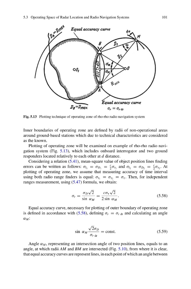
Fig. 5.13 Plotting technique of operating zone of rho-rho radio navigation system
Inner boundaries of operating zone are defined by radii of non-operational areas
around ground-based stations which due to technical characteristics are considered
as the known.
Plotting of operating zone will be examined on example of rho-rho radio navigation system (Fig. 5.13), which includes onboard interrogator and two ground
responders located relatively to each other at d distance.
Considering a relation (5.41), mean-square value of object position lines finding
errors can be written as follows: σ l 1 = σ D 1 =
c
2
σ τ 1 and σ l 2 = σ D 2 =
c
2
σ τ 2 . At
plotting of operating zone, we assume that measuring accuracy of time interval
using both radio range finders is equal: σ τ 1 = σ τ 2 = σ τ . Then, for independent
ranges measurement, using (5.47) formula, we obtain:
σ r =
σ D
√
2
sin α M
=
cσ τ
√
2
2 sin α M
.
(5.58)
Equal accuracy curve, necessary for plotting of outer boundary of operating zone
is defined in accordance with (5.58), defining σ r = σ r dr and calculating an angle
α M :
sin α M
√
2σ D
σ r dr
= const.
(5.59)
Angle α M , representing an intersection angle of two position lines, equals to an
angle, at which radii AM and BM are intersected (Fig. 5.10), from where it is clear,
that equal accuracy curves are represent lines, in each point of which an angle between
101
Fig. 5.13 Plotting technique of operating zone of rho-rho radio navigation system
Inner boundaries of operating zone are defined by radii of non-operational areas
around ground-based stations which due to technical characteristics are considered
as the known.
Plotting of operating zone will be examined on example of rho-rho radio navigation system (Fig. 5.13), which includes onboard interrogator and two ground
responders located relatively to each other at d distance.
Considering a relation (5.41), mean-square value of object position lines finding
errors can be written as follows: σ l 1 = σ D 1 =
c
2
σ τ 1 and σ l 2 = σ D 2 =
c
2
σ τ 2 . At
plotting of operating zone, we assume that measuring accuracy of time interval
using both radio range finders is equal: σ τ 1 = σ τ 2 = σ τ . Then, for independent
ranges measurement, using (5.47) formula, we obtain:
σ r =
σ D
√
2
sin α M
=
cσ τ
√
2
2 sin α M
.
(5.58)
Equal accuracy curve, necessary for plotting of outer boundary of operating zone
is defined in accordance with (5.58), defining σ r = σ r dr and calculating an angle
α M :
sin α M
√
2σ D
σ r dr
= const.
(5.59)
Angle α M , representing an intersection angle of two position lines, equals to an
angle, at which radii AM and BM are intersected (Fig. 5.10), from where it is clear,
that equal accuracy curves are represent lines, in each point of which an angle between