

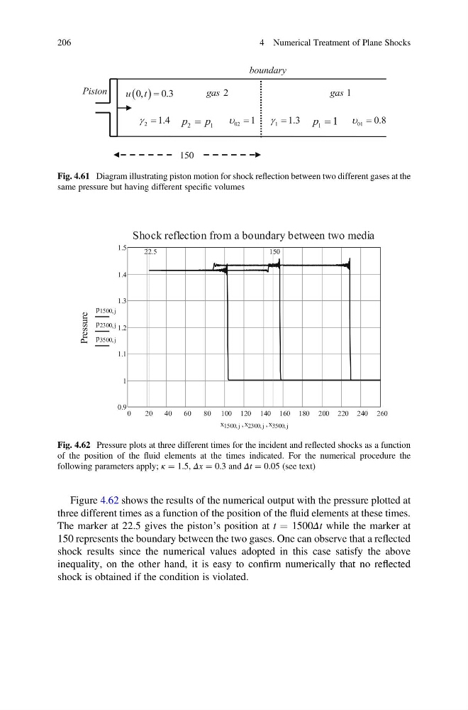
Figure 4.62 shows the results of the numerical output with the pressure plotted at
three different times as a function of the position of the fluid elements at these times.
The marker at 22.5 gives the piston’s position at t ¼ 1500Δt while the marker at
150 represents the boundary between the two gases. One can observe that a reflected
shock results since the numerical values adopted in this case satisfy the above
inequality, on the other hand, it is easy to confirm numerically that no reflected
shock is obtained if the condition is violated.
Fig. 4.61 Diagram illustrating piston motion for shock reflection between two different gases at the
same pressure but having different specific volumes
Fig. 4.62 Pressure plots at three different times for the incident and reflected shocks as a function
of the position of the fluid elements at the times indicated. For the numerical procedure the
following parameters apply; κ ¼ 1.5, Δx ¼ 0.3 and Δt ¼ 0.05 (see text)
206
4 Numerical Treatment of Plane Shocks
three different times as a function of the position of the fluid elements at these times.
The marker at 22.5 gives the piston’s position at t ¼ 1500Δt while the marker at
150 represents the boundary between the two gases. One can observe that a reflected
shock results since the numerical values adopted in this case satisfy the above
inequality, on the other hand, it is easy to confirm numerically that no reflected
shock is obtained if the condition is violated.
Fig. 4.61 Diagram illustrating piston motion for shock reflection between two different gases at the
same pressure but having different specific volumes
Fig. 4.62 Pressure plots at three different times for the incident and reflected shocks as a function
of the position of the fluid elements at the times indicated. For the numerical procedure the
following parameters apply; κ ¼ 1.5, Δx ¼ 0.3 and Δt ¼ 0.05 (see text)
206
4 Numerical Treatment of Plane Shocks