

propagate at this speed, consequently, the profile retains its shape with the passage of
time. However, when the amplitude of the disturbance increases, as observed in
Chap. 2, this behaviour no longer applies as different parts of the profile propagate at
different speeds and the profile changes its shape and becomes distorted as it
propagates. We will now investigate the effect of amplitude distortion numerically
by considering the propagation of a single sinusoidal pulse down a tube that is
generated by appropriate piston motion and we will follow the progress of the
disturbance as it moves away from the source. In this context, it is useful to recall
our discussion of acoustic wave distortion that was presented at the end of Sect. 1.8.
Initially, we will assume that the disturbance has small amplitude and we will then
proceed to increase the amplitude and observe the changes taking place in the profile.
Let us assume that the velocity of the piston can be represented by the equation,
u 0, t
ð Þ ¼ u m Sin aπt
ð Þ for 1=a
ð
Þ ! t ! 0
¼ 0 for t > 1=a,
where u m is the maximum amplitude of the velocity. Assuming unity values for the
ambient pressure and density within the tube and by taking γ ¼ 1.4 we find that the
velocity of sound is
ffiffi ffi
γ
p ¼ 1:18. In order to carry out the numerical procedure the
following parameters are assumed; κ ¼ 1.2, a ¼ 0.04, Δx ¼ 0.3 (Arb. units) and
Δt ¼ 0.05 (Arb. units). Initially, we will assume that u m ¼ 0.01 (Arb. units) which is
Position (Arb.units)
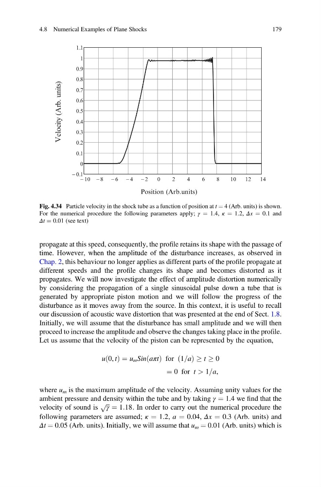
Fig. 4.34 Particle velocity in the shock tube as a function of position at t ¼ 4 (Arb. units) is shown.
For the numerical procedure the following parameters apply; γ ¼ 1.4, κ ¼ 1.2, Δx ¼ 0.1 and
Δt ¼ 0.01 (see text)
4.8 Numerical Examples of Plane Shocks
179
time. However, when the amplitude of the disturbance increases, as observed in
Chap. 2, this behaviour no longer applies as different parts of the profile propagate at
different speeds and the profile changes its shape and becomes distorted as it
propagates. We will now investigate the effect of amplitude distortion numerically
by considering the propagation of a single sinusoidal pulse down a tube that is
generated by appropriate piston motion and we will follow the progress of the
disturbance as it moves away from the source. In this context, it is useful to recall
our discussion of acoustic wave distortion that was presented at the end of Sect. 1.8.
Initially, we will assume that the disturbance has small amplitude and we will then
proceed to increase the amplitude and observe the changes taking place in the profile.
Let us assume that the velocity of the piston can be represented by the equation,
u 0, t
ð Þ ¼ u m Sin aπt
ð Þ for 1=a
ð
Þ ! t ! 0
¼ 0 for t > 1=a,
where u m is the maximum amplitude of the velocity. Assuming unity values for the
ambient pressure and density within the tube and by taking γ ¼ 1.4 we find that the
velocity of sound is
ffiffi ffi
γ
p ¼ 1:18. In order to carry out the numerical procedure the
following parameters are assumed; κ ¼ 1.2, a ¼ 0.04, Δx ¼ 0.3 (Arb. units) and
Δt ¼ 0.05 (Arb. units). Initially, we will assume that u m ¼ 0.01 (Arb. units) which is
Position (Arb.units)
Fig. 4.34 Particle velocity in the shock tube as a function of position at t ¼ 4 (Arb. units) is shown.
For the numerical procedure the following parameters apply; γ ¼ 1.4, κ ¼ 1.2, Δx ¼ 0.1 and
Δt ¼ 0.01 (see text)
4.8 Numerical Examples of Plane Shocks
179