

corresponding to n ¼ 1000, namely, u 1000, j , p 1000, j and 1/υ 1000, j shows particle
velocity, pressure and density, respectively, as a function of position for the advancing incident shock front towards the closed end. As before, using Eq. (3.40) and
writing U s ¼ U i for the incident shock, we have,
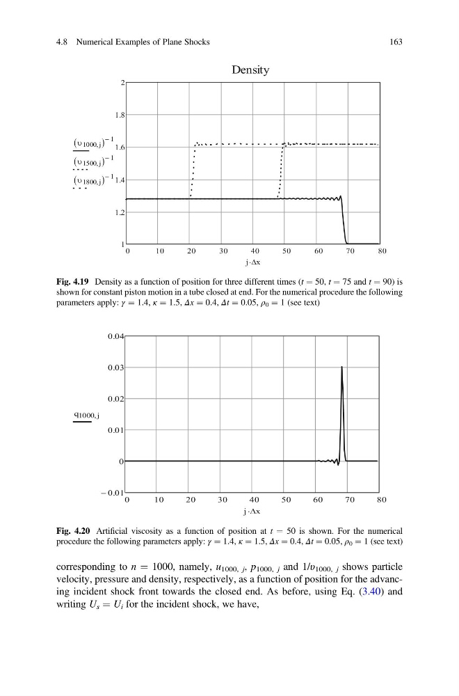
Fig. 4.19 Density as a function of position for three different times (t ¼ 50, t ¼ 75 and t ¼ 90) is
shown for constant piston motion in a tube closed at end. For the numerical procedure the following
parameters apply: γ ¼ 1.4, κ ¼ 1.5, Δx ¼ 0.4, Δt ¼ 0.05, ρ 0 ¼ 1 (see text)
Fig. 4.20 Artificial viscosity as a function of position at t ¼ 50 is shown. For the numerical
procedure the following parameters apply: γ ¼ 1.4, κ ¼ 1.5, Δx ¼ 0.4, Δt ¼ 0.05, ρ 0 ¼ 1 (see text)
4.8 Numerical Examples of Plane Shocks
163
velocity, pressure and density, respectively, as a function of position for the advancing incident shock front towards the closed end. As before, using Eq. (3.40) and
writing U s ¼ U i for the incident shock, we have,
Fig. 4.19 Density as a function of position for three different times (t ¼ 50, t ¼ 75 and t ¼ 90) is
shown for constant piston motion in a tube closed at end. For the numerical procedure the following
parameters apply: γ ¼ 1.4, κ ¼ 1.5, Δx ¼ 0.4, Δt ¼ 0.05, ρ 0 ¼ 1 (see text)
Fig. 4.20 Artificial viscosity as a function of position at t ¼ 50 is shown. For the numerical
procedure the following parameters apply: γ ¼ 1.4, κ ¼ 1.5, Δx ¼ 0.4, Δt ¼ 0.05, ρ 0 ¼ 1 (see text)
4.8 Numerical Examples of Plane Shocks
163