

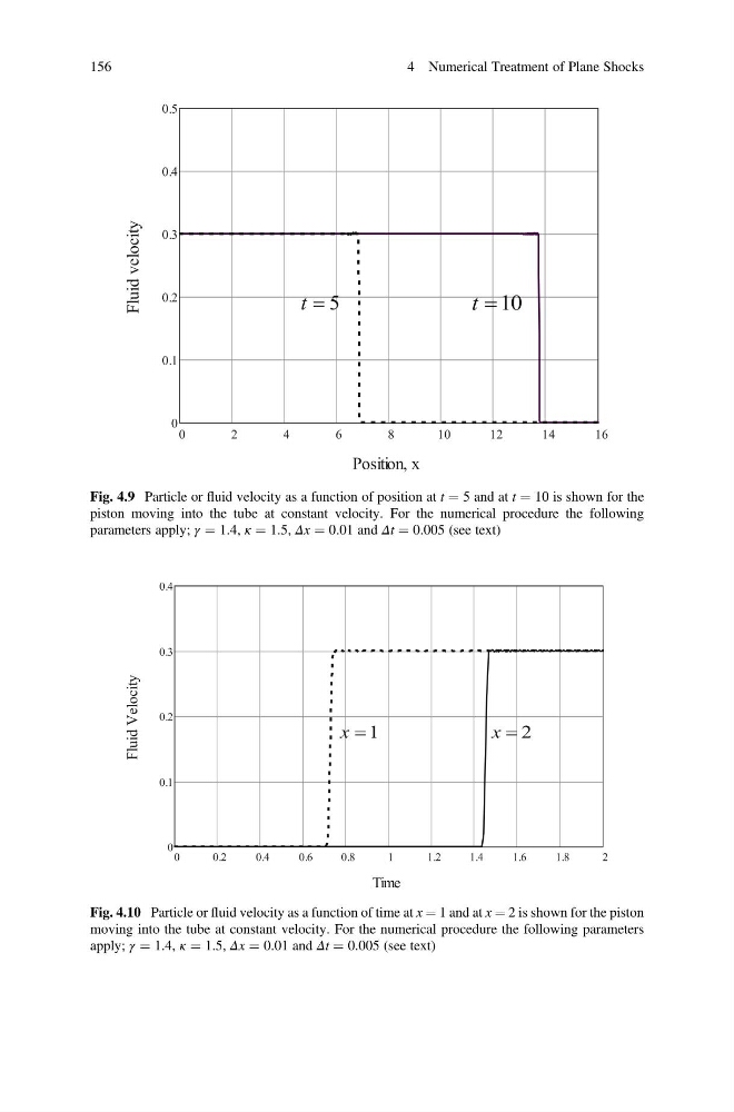
Fig. 4.9 Particle or fluid velocity as a function of position at t ¼ 5 and at t ¼ 10 is shown for the
piston moving into the tube at constant velocity. For the numerical procedure the following
parameters apply; γ ¼ 1.4, κ ¼ 1.5, Δx ¼ 0.01 and Δt ¼ 0.005 (see text)
Fig. 4.10 Particle or fluid velocity as a function of time at x ¼ 1 and at x ¼ 2 is shown for the piston
moving into the tube at constant velocity. For the numerical procedure the following parameters
apply; γ ¼ 1.4, κ ¼ 1.5, Δx ¼ 0.01 and Δt ¼ 0.005 (see text)
156
4 Numerical Treatment of Plane Shocks
piston moving into the tube at constant velocity. For the numerical procedure the following
parameters apply; γ ¼ 1.4, κ ¼ 1.5, Δx ¼ 0.01 and Δt ¼ 0.005 (see text)
Fig. 4.10 Particle or fluid velocity as a function of time at x ¼ 1 and at x ¼ 2 is shown for the piston
moving into the tube at constant velocity. For the numerical procedure the following parameters
apply; γ ¼ 1.4, κ ¼ 1.5, Δx ¼ 0.01 and Δt ¼ 0.005 (see text)
156
4 Numerical Treatment of Plane Shocks