

76
W. C. Law and S. De W. Wong
where n is the index of the perpendicular standing spin wave [152].
The rudimentary form of a FMR spectrometer would require a microwave source,
a microwave detector, an external magnetic field generated by an external magnetic
field, and a transmission line or a cavity to allow interaction between the sample
to and the microwave. In earlier versions of the experimental setup, a microwave
resonant cavity was used to produce a standing wave with a uniform ac field of the
microwave source h ac for the sample to be placed within [179, 184]. The cavity is
placed under an external magnetic field which is modulated with a Helmholtz coil
operating within a few tens of Hz. The modulated signal is picked up by the lock-in
amplifier, which measures the in-phase and quadrature voltage. Due to the physical
limitation of the length of the cavity to form uniform standing modes, relatively few
data points can be extracted.
Recent advancements have led to the usage of vector network analyzer (VNA)
along with a transmission line to perform broadband microwave spectroscopy. Due
to the quasi-static TEM mode characteristic of transmission lines such as grounded
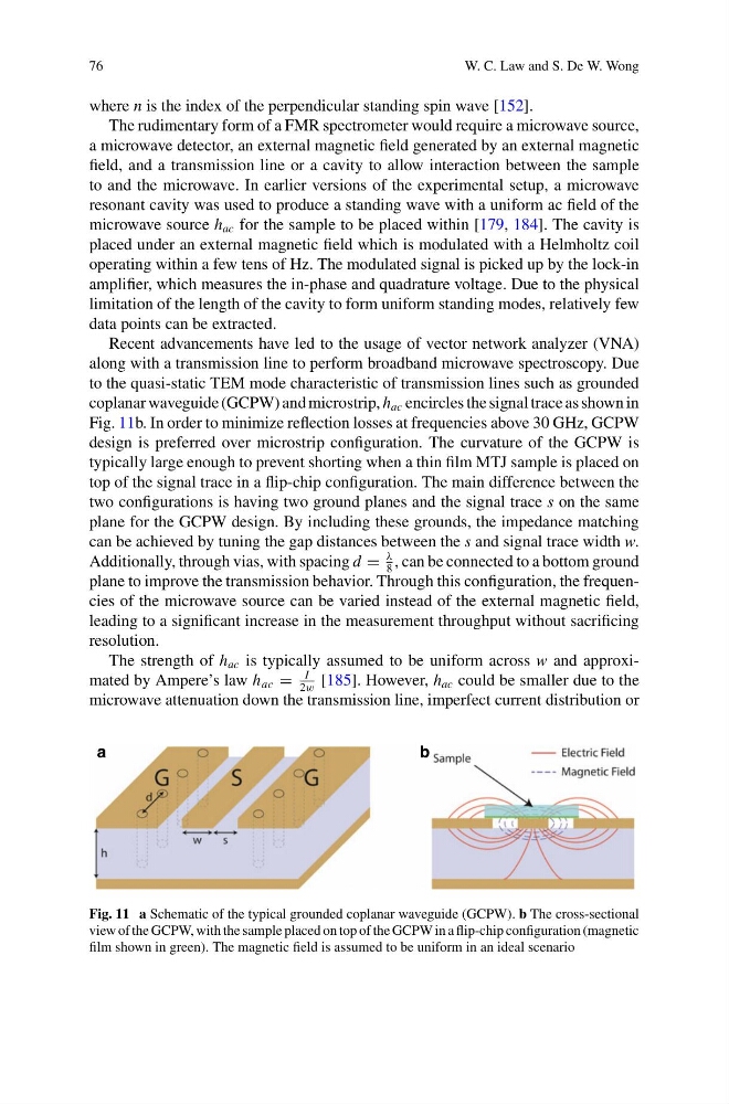
coplanar waveguide (GCPW) and microstrip, h ac encircles the signal trace as shown in
Fig. 11b. In order to minimize reflection losses at frequencies above 30 GHz, GCPW
design is preferred over microstrip configuration. The curvature of the GCPW is
typically large enough to prevent shorting when a thin film MTJ sample is placed on
top of the signal trace in a flip-chip configuration. The main difference between the
two configurations is having two ground planes and the signal trace s on the same
plane for the GCPW design. By including these grounds, the impedance matching
can be achieved by tuning the gap distances between the s and signal trace width w.
Additionally, through vias, with spacing d =
λ
8
, can be connected to a bottom ground
plane to improve the transmission behavior. Through this configuration, the frequencies of the microwave source can be varied instead of the external magnetic field,
leading to a significant increase in the measurement throughput without sacrificing
resolution.
The strength of h ac is typically assumed to be uniform across w and approximated by Ampere’s law h ac =
I
2w
[185]. However, h ac could be smaller due to the
microwave attenuation down the transmission line, imperfect current distribution or
a
b
Fig. 11 a Schematic of the typical grounded coplanar waveguide (GCPW). b The cross-sectional
view of the GCPW, with the sample placed on top of the GCPW in a flip-chip configuration (magnetic
film shown in green). The magnetic field is assumed to be uniform in an ideal scenario
W. C. Law and S. De W. Wong
where n is the index of the perpendicular standing spin wave [152].
The rudimentary form of a FMR spectrometer would require a microwave source,
a microwave detector, an external magnetic field generated by an external magnetic
field, and a transmission line or a cavity to allow interaction between the sample
to and the microwave. In earlier versions of the experimental setup, a microwave
resonant cavity was used to produce a standing wave with a uniform ac field of the
microwave source h ac for the sample to be placed within [179, 184]. The cavity is
placed under an external magnetic field which is modulated with a Helmholtz coil
operating within a few tens of Hz. The modulated signal is picked up by the lock-in
amplifier, which measures the in-phase and quadrature voltage. Due to the physical
limitation of the length of the cavity to form uniform standing modes, relatively few
data points can be extracted.
Recent advancements have led to the usage of vector network analyzer (VNA)
along with a transmission line to perform broadband microwave spectroscopy. Due
to the quasi-static TEM mode characteristic of transmission lines such as grounded
coplanar waveguide (GCPW) and microstrip, h ac encircles the signal trace as shown in
Fig. 11b. In order to minimize reflection losses at frequencies above 30 GHz, GCPW
design is preferred over microstrip configuration. The curvature of the GCPW is
typically large enough to prevent shorting when a thin film MTJ sample is placed on
top of the signal trace in a flip-chip configuration. The main difference between the
two configurations is having two ground planes and the signal trace s on the same
plane for the GCPW design. By including these grounds, the impedance matching
can be achieved by tuning the gap distances between the s and signal trace width w.
Additionally, through vias, with spacing d =
λ
8
, can be connected to a bottom ground
plane to improve the transmission behavior. Through this configuration, the frequencies of the microwave source can be varied instead of the external magnetic field,
leading to a significant increase in the measurement throughput without sacrificing
resolution.
The strength of h ac is typically assumed to be uniform across w and approximated by Ampere’s law h ac =
I
2w
[185]. However, h ac could be smaller due to the
microwave attenuation down the transmission line, imperfect current distribution or
a
b
Fig. 11 a Schematic of the typical grounded coplanar waveguide (GCPW). b The cross-sectional
view of the GCPW, with the sample placed on top of the GCPW in a flip-chip configuration (magnetic
film shown in green). The magnetic field is assumed to be uniform in an ideal scenario