

Resistive Random Access Memory Device …
321
will be discussed with respect to the selector device and the self-rectifying RRAM
implementations. It will then end with a conclusion and future outlook.
2 RRAM Device and Operation
A typical RRAM device has a simple metal-insulator-metal (MIM) structure,
whereby the sandwiched insulator is the active layer that stores the data. In general,
a RRAM device is able to show two distinct resistance levels, namely the high resistance state (HRS) and the low resistance state (LRS), which represent the logic ‘0’
and logic ‘1’, respectively. More than two resistance levels can also be obtained via
careful tuning of the programming voltage pulse width and amplitude, which leads
to high data storage density.
The two basic RRAM operations are programming and erasing. The transition
from HRS to LRS is known as the SET or programming operation. Conversely,
the RESET or erasing operation denotes the transition from LRS to HRS. Usually,
a pristine RRAM device will have an initial high resistance which requires an
applied voltage that is higher than the SET voltage to activate the resistive switching
capability. This event is called the electroforming or forming process.
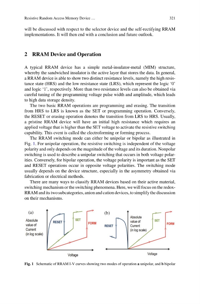
The RRAM switching mode can either be unipolar or bipolar as illustrated in
Fig. 1. For unipolar operation, the resistive switching is independent of the voltage
polarity and only depends on the magnitude of the voltage and its duration. Nonpolar
switching is used to describe a unipolar switching that occurs in both voltage polarities. Conversely, for bipolar operation, the voltage polarity is important as the SET
and RESET operations occur in opposite voltage polarities. The switching mode
usually depends on the device structure, especially in the asymmetry obtained via
fabrication or electrical methods.
There are many ways to classify RRAM devices based on their active material,
switching mechanism or the switching phenomena. Here, we will focus on the redoxRRAM and its two subcategories, anion and cation devices, to simplify the discussion
on their mechanisms.
Fig. 1 Schematic of RRAM I-V curves showing two modes of operation a unipolar, and b bipolar
321
will be discussed with respect to the selector device and the self-rectifying RRAM
implementations. It will then end with a conclusion and future outlook.
2 RRAM Device and Operation
A typical RRAM device has a simple metal-insulator-metal (MIM) structure,
whereby the sandwiched insulator is the active layer that stores the data. In general,
a RRAM device is able to show two distinct resistance levels, namely the high resistance state (HRS) and the low resistance state (LRS), which represent the logic ‘0’
and logic ‘1’, respectively. More than two resistance levels can also be obtained via
careful tuning of the programming voltage pulse width and amplitude, which leads
to high data storage density.
The two basic RRAM operations are programming and erasing. The transition
from HRS to LRS is known as the SET or programming operation. Conversely,
the RESET or erasing operation denotes the transition from LRS to HRS. Usually,
a pristine RRAM device will have an initial high resistance which requires an
applied voltage that is higher than the SET voltage to activate the resistive switching
capability. This event is called the electroforming or forming process.
The RRAM switching mode can either be unipolar or bipolar as illustrated in
Fig. 1. For unipolar operation, the resistive switching is independent of the voltage
polarity and only depends on the magnitude of the voltage and its duration. Nonpolar
switching is used to describe a unipolar switching that occurs in both voltage polarities. Conversely, for bipolar operation, the voltage polarity is important as the SET
and RESET operations occur in opposite voltage polarities. The switching mode
usually depends on the device structure, especially in the asymmetry obtained via
fabrication or electrical methods.
There are many ways to classify RRAM devices based on their active material,
switching mechanism or the switching phenomena. Here, we will focus on the redoxRRAM and its two subcategories, anion and cation devices, to simplify the discussion
on their mechanisms.
Fig. 1 Schematic of RRAM I-V curves showing two modes of operation a unipolar, and b bipolar