

Circuit Design for Non-volatile Magnetic Memory
217
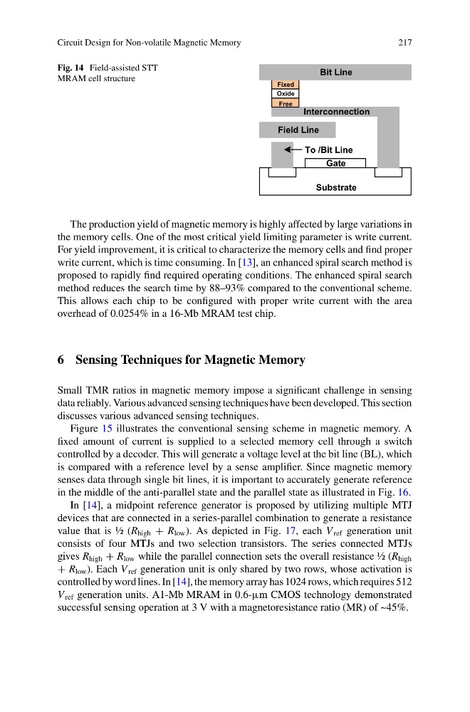
Fig. 14 Field-assisted STT
MRAM cell structure
Substrate
Gate
Free
Oxide
Fixed
Bit Line
Interconnection
Field Line
To /Bit Line
The production yield of magnetic memory is highly affected by large variations in
the memory cells. One of the most critical yield limiting parameter is write current.
For yield improvement, it is critical to characterize the memory cells and find proper
write current, which is time consuming. In [13], an enhanced spiral search method is
proposed to rapidly find required operating conditions. The enhanced spiral search
method reduces the search time by 88–93% compared to the conventional scheme.
This allows each chip to be configured with proper write current with the area
overhead of 0.0254% in a 16-Mb MRAM test chip.
6 Sensing Techniques for Magnetic Memory
Small TMR ratios in magnetic memory impose a significant challenge in sensing
data reliably. Various advanced sensing techniques have been developed. This section
discusses various advanced sensing techniques.
Figure 15 illustrates the conventional sensing scheme in magnetic memory. A
fixed amount of current is supplied to a selected memory cell through a switch
controlled by a decoder. This will generate a voltage level at the bit line (BL), which
is compared with a reference level by a sense amplifier. Since magnetic memory
senses data through single bit lines, it is important to accurately generate reference
in the middle of the anti-parallel state and the parallel state as illustrated in Fig. 16.
In [14], a midpoint reference generator is proposed by utilizing multiple MTJ
devices that are connected in a series-parallel combination to generate a resistance
value that is ½ (R high + R low ). As depicted in Fig. 17, each V ref generation unit
consists of four MTJs and two selection transistors. The series connected MTJs
gives R high + R low while the parallel connection sets the overall resistance ½ (R high
+ R low ). Each V ref generation unit is only shared by two rows, whose activation is
controlled by word lines. In [14], the memory array has 1024 rows, which requires 512
V ref generation units. A1-Mb MRAM in 0.6-µm CMOS technology demonstrated
successful sensing operation at 3 V with a magnetoresistance ratio (MR) of ~45%.
217
Fig. 14 Field-assisted STT
MRAM cell structure
Substrate
Gate
Free
Oxide
Fixed
Bit Line
Interconnection
Field Line
To /Bit Line
The production yield of magnetic memory is highly affected by large variations in
the memory cells. One of the most critical yield limiting parameter is write current.
For yield improvement, it is critical to characterize the memory cells and find proper
write current, which is time consuming. In [13], an enhanced spiral search method is
proposed to rapidly find required operating conditions. The enhanced spiral search
method reduces the search time by 88–93% compared to the conventional scheme.
This allows each chip to be configured with proper write current with the area
overhead of 0.0254% in a 16-Mb MRAM test chip.
6 Sensing Techniques for Magnetic Memory
Small TMR ratios in magnetic memory impose a significant challenge in sensing
data reliably. Various advanced sensing techniques have been developed. This section
discusses various advanced sensing techniques.
Figure 15 illustrates the conventional sensing scheme in magnetic memory. A
fixed amount of current is supplied to a selected memory cell through a switch
controlled by a decoder. This will generate a voltage level at the bit line (BL), which
is compared with a reference level by a sense amplifier. Since magnetic memory
senses data through single bit lines, it is important to accurately generate reference
in the middle of the anti-parallel state and the parallel state as illustrated in Fig. 16.
In [14], a midpoint reference generator is proposed by utilizing multiple MTJ
devices that are connected in a series-parallel combination to generate a resistance
value that is ½ (R high + R low ). As depicted in Fig. 17, each V ref generation unit
consists of four MTJs and two selection transistors. The series connected MTJs
gives R high + R low while the parallel connection sets the overall resistance ½ (R high
+ R low ). Each V ref generation unit is only shared by two rows, whose activation is
controlled by word lines. In [14], the memory array has 1024 rows, which requires 512
V ref generation units. A1-Mb MRAM in 0.6-µm CMOS technology demonstrated
successful sensing operation at 3 V with a magnetoresistance ratio (MR) of ~45%.