

Microwave Oscillators and Detectors Based …
15
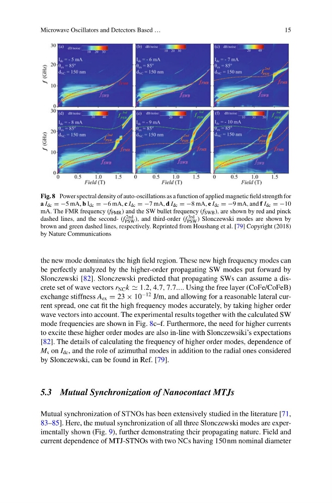
Fig. 8 Power spectral density of auto-oscillations as a function of applied magnetic field strength for
a I dc = −5 mA, b I dc = −6 mA, c I dc = −7 mA, d I dc = −8 mA, e I dc = −9 mA, and f I dc = −10
mA. The FMR frequency (f FMR ) and the SW bullet frequency (f SWB ), are shown by red and pinck
dashed lines, and the second- (f 2nd
PSW ), and third-order (f 3rd
PSW ) Slonczewski modes are shown by
brown and green dashed lines, respectively. Reprinted from Houshang et al. [79] Copyright (2018)
by Nature Communications
the new mode dominates the high field region. These new high frequency modes can
be perfectly analyzed by the higher-order propagating SW modes put forward by
Slonczewski [82]. Slonczewski predicted that propagating SWs can assume a discrete set of wave vectors r NC k 1.2, 4.7, 7.7.... Using the free layer (CoFe/CoFeB)
exchange stiffness A ex = 23 × 10
−12 J/m, and allowing for a reasonable lateral current spread, one cat fit the high frequency modes accurately, by taking higher order
wave vectors into account. The experimental results together with the calculated SW
mode frequencies are shown in Fig. 8c–f. Furthermore, the need for higher currents
to excite these higher order modes are also in-line with Slonczewsiki’s expectations
[82]. The details of calculating the frequency of higher order modes, dependence of
M s on I dc , and the role of azimuthal modes in addition to the radial ones considered
by Slonczewski, can be found in Ref. [79].
5.3 Mutual Synchronization of Nanocontact MTJs
Mutual synchronization of STNOs has been extensively studied in the literature [71,
83–85]. Here, the mutual synchronization of all three Slonczewski modes are experimentally shown (Fig. 9), further demonstrating their propagating nature. Field and
current dependence of MTJ-STNOs with two NCs having 150 nm nominal diameter
15
Fig. 8 Power spectral density of auto-oscillations as a function of applied magnetic field strength for
a I dc = −5 mA, b I dc = −6 mA, c I dc = −7 mA, d I dc = −8 mA, e I dc = −9 mA, and f I dc = −10
mA. The FMR frequency (f FMR ) and the SW bullet frequency (f SWB ), are shown by red and pinck
dashed lines, and the second- (f 2nd
PSW ), and third-order (f 3rd
PSW ) Slonczewski modes are shown by
brown and green dashed lines, respectively. Reprinted from Houshang et al. [79] Copyright (2018)
by Nature Communications
the new mode dominates the high field region. These new high frequency modes can
be perfectly analyzed by the higher-order propagating SW modes put forward by
Slonczewski [82]. Slonczewski predicted that propagating SWs can assume a discrete set of wave vectors r NC k 1.2, 4.7, 7.7.... Using the free layer (CoFe/CoFeB)
exchange stiffness A ex = 23 × 10
−12 J/m, and allowing for a reasonable lateral current spread, one cat fit the high frequency modes accurately, by taking higher order
wave vectors into account. The experimental results together with the calculated SW
mode frequencies are shown in Fig. 8c–f. Furthermore, the need for higher currents
to excite these higher order modes are also in-line with Slonczewsiki’s expectations
[82]. The details of calculating the frequency of higher order modes, dependence of
M s on I dc , and the role of azimuthal modes in addition to the radial ones considered
by Slonczewski, can be found in Ref. [79].
5.3 Mutual Synchronization of Nanocontact MTJs
Mutual synchronization of STNOs has been extensively studied in the literature [71,
83–85]. Here, the mutual synchronization of all three Slonczewski modes are experimentally shown (Fig. 9), further demonstrating their propagating nature. Field and
current dependence of MTJ-STNOs with two NCs having 150 nm nominal diameter