

14
P. K. Muduli et al.
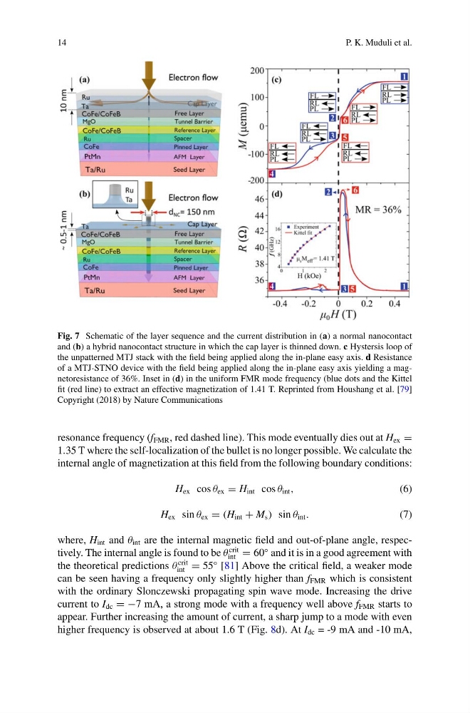
Fig. 7 Schematic of the layer sequence and the current distribution in (a) a normal nanocontact
and (b) a hybrid nanocontact structure in which the cap layer is thinned down. c Hystersis loop of
the unpatterned MTJ stack with the field being applied along the in-plane easy axis. d Resistance
of a MTJ-STNO device with the field being applied along the in-plane easy axis yielding a magnetoresistance of 36%. Inset in (d) in the uniform FMR mode frequency (blue dots and the Kittel
fit (red line) to extract an effective magnetization of 1.41 T. Reprinted from Houshang et al. [79]
Copyright (2018) by Nature Communications
resonance frequency (f FMR , red dashed line). This mode eventually dies out at H ex =
1.35 T where the self-localization of the bullet is no longer possible. We calculate the
internal angle of magnetization at this field from the following boundary conditions:
H ex cos θ ex = H int cos θ int ,
(6)
H ex sin θ ex = (H int + M s ) sin θ int .
(7)
where, H int and θ int are the internal magnetic field and out-of-plane angle, respectively. The internal angle is found to be θ
crit
int = 60
◦ and it is in a good agreement with
the theoretical predictions θ
crit
int = 55
◦ [81] Above the critical field, a weaker mode
can be seen having a frequency only slightly higher than f FMR which is consistent
with the ordinary Slonczewski propagating spin wave mode. Increasing the drive
current to I dc = −7 mA, a strong mode with a frequency well above f FMR starts to
appear. Further increasing the amount of current, a sharp jump to a mode with even
higher frequency is observed at about 1.6 T (Fig. 8d). At I dc = -9 mA and -10 mA,
P. K. Muduli et al.
Fig. 7 Schematic of the layer sequence and the current distribution in (a) a normal nanocontact
and (b) a hybrid nanocontact structure in which the cap layer is thinned down. c Hystersis loop of
the unpatterned MTJ stack with the field being applied along the in-plane easy axis. d Resistance
of a MTJ-STNO device with the field being applied along the in-plane easy axis yielding a magnetoresistance of 36%. Inset in (d) in the uniform FMR mode frequency (blue dots and the Kittel
fit (red line) to extract an effective magnetization of 1.41 T. Reprinted from Houshang et al. [79]
Copyright (2018) by Nature Communications
resonance frequency (f FMR , red dashed line). This mode eventually dies out at H ex =
1.35 T where the self-localization of the bullet is no longer possible. We calculate the
internal angle of magnetization at this field from the following boundary conditions:
H ex cos θ ex = H int cos θ int ,
(6)
H ex sin θ ex = (H int + M s ) sin θ int .
(7)
where, H int and θ int are the internal magnetic field and out-of-plane angle, respectively. The internal angle is found to be θ
crit
int = 60
◦ and it is in a good agreement with
the theoretical predictions θ
crit
int = 55
◦ [81] Above the critical field, a weaker mode
can be seen having a frequency only slightly higher than f FMR which is consistent
with the ordinary Slonczewski propagating spin wave mode. Increasing the drive
current to I dc = −7 mA, a strong mode with a frequency well above f FMR starts to
appear. Further increasing the amount of current, a sharp jump to a mode with even
higher frequency is observed at about 1.6 T (Fig. 8d). At I dc = -9 mA and -10 mA,