

Chiral Magnetic Domain Wall and Skyrmion Memory Devices
185
where W is the half width half maximum line width, H FMR is the resonance field,
S is the symmetric Lorentzian coefficient, and A is the antisymmetric Lorentzian
coefficient. The ratio of S to A can be used to evaluate the ratio of the damping-like
torque to the effective field from the Oersted field and the field-like torque. In order
to decouple these two the magnitude of the rf current in the bilayer has to be known.
For a more reliable quantification of the SOTs an additional dc-current modulation
and thickness dependence of magnetic thin films should be measured [36, 38, 39]. By
measuring the ST-FMR with an additional dc current, the damping-like torque can
be quantified with the dependence of the linewidth on the dc current. Additionally,
the change in the resonance field yields a direct measurement of the field-like torque.
2.1.2 Higher-Order Harmonics Measurements
Another widely used method in measuring SOTs is using the second harmonic
measurements of electrical transport. By probing the Hall measurements using an ac
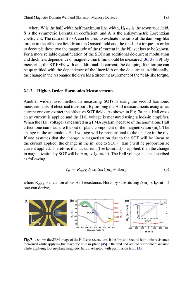
current one can extract the effective SOT fields. As shown in Fig. 7a, in a Hall cross
an ac current is applied and the Hall voltage is measured using a lock-in amplifier.
When the Hall voltage is measured in a PMA system, because of the anomalous Hall
effect, one can measure the out of plane component of the magnetization (m z ). The
change in the anomalous Hall voltage will be proportional to the change in the m z .
If one assumes that the change in magnetization due to the SOT will be linear to
the current applied, the change in the m z due to SOT (=m z ) will be proportion ac
current applied. Therefore, if an ac current (I = I 0 sin(ωt)) is applied, then the change
in magnetization by SOT will be m z ∝ I 0 sin(ωt). The Hall voltage can be described
as following,
V H = R AH E I 0 sin(ωt)(m z + m z )
(3)
where R AHE is the anomalous Hall resistance. Here, by substituting m z ∝ I 0 sin(ωt)
one can derive,
Fig. 7 a shows the SEM image of the Hall cross structure. b the first and second harmonic resistance
measured while applying the magnetic field in-plane [45]. c the first and second harmonic resistance
while applying low in-plane magnetic fields. Adapted with permission from [45]
185
where W is the half width half maximum line width, H FMR is the resonance field,
S is the symmetric Lorentzian coefficient, and A is the antisymmetric Lorentzian
coefficient. The ratio of S to A can be used to evaluate the ratio of the damping-like
torque to the effective field from the Oersted field and the field-like torque. In order
to decouple these two the magnitude of the rf current in the bilayer has to be known.
For a more reliable quantification of the SOTs an additional dc-current modulation
and thickness dependence of magnetic thin films should be measured [36, 38, 39]. By
measuring the ST-FMR with an additional dc current, the damping-like torque can
be quantified with the dependence of the linewidth on the dc current. Additionally,
the change in the resonance field yields a direct measurement of the field-like torque.
2.1.2 Higher-Order Harmonics Measurements
Another widely used method in measuring SOTs is using the second harmonic
measurements of electrical transport. By probing the Hall measurements using an ac
current one can extract the effective SOT fields. As shown in Fig. 7a, in a Hall cross
an ac current is applied and the Hall voltage is measured using a lock-in amplifier.
When the Hall voltage is measured in a PMA system, because of the anomalous Hall
effect, one can measure the out of plane component of the magnetization (m z ). The
change in the anomalous Hall voltage will be proportional to the change in the m z .
If one assumes that the change in magnetization due to the SOT will be linear to
the current applied, the change in the m z due to SOT (=m z ) will be proportion ac
current applied. Therefore, if an ac current (I = I 0 sin(ωt)) is applied, then the change
in magnetization by SOT will be m z ∝ I 0 sin(ωt). The Hall voltage can be described
as following,
V H = R AH E I 0 sin(ωt)(m z + m z )
(3)
where R AHE is the anomalous Hall resistance. Here, by substituting m z ∝ I 0 sin(ωt)
one can derive,
Fig. 7 a shows the SEM image of the Hall cross structure. b the first and second harmonic resistance
measured while applying the magnetic field in-plane [45]. c the first and second harmonic resistance
while applying low in-plane magnetic fields. Adapted with permission from [45]