

164
J. Lourembam and J. Huang
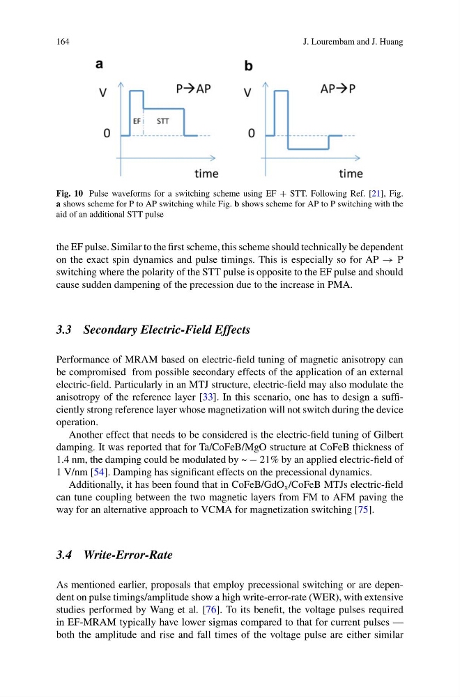
Fig. 10 Pulse waveforms for a switching scheme using EF + STT. Following Ref. [21], Fig.
a shows scheme for P to AP switching while Fig. b shows scheme for AP to P switching with the
aid of an additional STT pulse
the EF pulse. Similar to the first scheme, this scheme should technically be dependent
on the exact spin dynamics and pulse timings. This is especially so for AP → P
switching where the polarity of the STT pulse is opposite to the EF pulse and should
cause sudden dampening of the precession due to the increase in PMA.
3.3 Secondary Electric-Field Effects
Performance of MRAM based on electric-field tuning of magnetic anisotropy can
be compromised from possible secondary effects of the application of an external
electric-field. Particularly in an MTJ structure, electric-field may also modulate the
anisotropy of the reference layer [33]. In this scenario, one has to design a sufficiently strong reference layer whose magnetization will not switch during the device
operation.
Another effect that needs to be considered is the electric-field tuning of Gilbert
damping. It was reported that for Ta/CoFeB/MgO structure at CoFeB thickness of
1.4 nm, the damping could be modulated by ~ − 21% by an applied electric-field of
1 V/nm [54]. Damping has significant effects on the precessional dynamics.
Additionally, it has been found that in CoFeB/GdO x /CoFeB MTJs electric-field
can tune coupling between the two magnetic layers from FM to AFM paving the
way for an alternative approach to VCMA for magnetization switching [75].
3.4 Write-Error-Rate
As mentioned earlier, proposals that employ precessional switching or are dependent on pulse timings/amplitude show a high write-error-rate (WER), with extensive
studies performed by Wang et al. [76]. To its benefit, the voltage pulses required
in EF-MRAM typically have lower sigmas compared to that for current pulses —
both the amplitude and rise and fall times of the voltage pulse are either similar
J. Lourembam and J. Huang
Fig. 10 Pulse waveforms for a switching scheme using EF + STT. Following Ref. [21], Fig.
a shows scheme for P to AP switching while Fig. b shows scheme for AP to P switching with the
aid of an additional STT pulse
the EF pulse. Similar to the first scheme, this scheme should technically be dependent
on the exact spin dynamics and pulse timings. This is especially so for AP → P
switching where the polarity of the STT pulse is opposite to the EF pulse and should
cause sudden dampening of the precession due to the increase in PMA.
3.3 Secondary Electric-Field Effects
Performance of MRAM based on electric-field tuning of magnetic anisotropy can
be compromised from possible secondary effects of the application of an external
electric-field. Particularly in an MTJ structure, electric-field may also modulate the
anisotropy of the reference layer [33]. In this scenario, one has to design a sufficiently strong reference layer whose magnetization will not switch during the device
operation.
Another effect that needs to be considered is the electric-field tuning of Gilbert
damping. It was reported that for Ta/CoFeB/MgO structure at CoFeB thickness of
1.4 nm, the damping could be modulated by ~ − 21% by an applied electric-field of
1 V/nm [54]. Damping has significant effects on the precessional dynamics.
Additionally, it has been found that in CoFeB/GdO x /CoFeB MTJs electric-field
can tune coupling between the two magnetic layers from FM to AFM paving the
way for an alternative approach to VCMA for magnetization switching [75].
3.4 Write-Error-Rate
As mentioned earlier, proposals that employ precessional switching or are dependent on pulse timings/amplitude show a high write-error-rate (WER), with extensive
studies performed by Wang et al. [76]. To its benefit, the voltage pulses required
in EF-MRAM typically have lower sigmas compared to that for current pulses —
both the amplitude and rise and fall times of the voltage pulse are either similar