

Electric-Field-Controlled MRAM: Physics and Applications
153
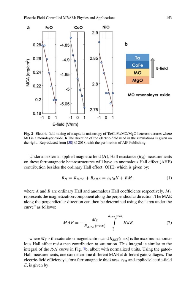
Fig. 2 Electric-field tuning of magnetic anisotropy of Ta/CoFe/MO/MgO heterostructures where
MO is a monolayer oxide. b The direction of the electric-field used in the simulations is given on
the right. Reproduced from [50] © 2018, with the permission of AIP Publishing
Under an external applied magnetic field (H), Hall resistance (R H ) measurements
on these ferromagnetic heterostructures will have an anomalous Hall effect (AHE)
contribution besides the ordinary Hall effect (OHE) which is given by:
R H = R O H E + R AH E = Aμ 0 H + B M ⊥
(1)
where A and B are ordinary Hall and anomalous Hall coefficients respectively. M ⊥
represents the magnetization component along the perpendicular direction. The MAE
along the perpendicular direction can then be determined using the “area under the
curve” as follows:
M AE = −
M S
R AH E (max)
R AH E (max)
0
Hd R
(2)
where M S is the saturation magnetization, and R AHE (max) is the maximum anomalous Hall effect resistance contribution at saturation. This integral is similar to the
integral of the R-H curve in Fig. 7b, albeit with normalized units. Using the gatedHall measurements, one can determine different MAE at different gate voltages. The
electric-field efficiency ξ for a ferromagnetic thickness, t FM and applied electric-field
E, is given by:
153
Fig. 2 Electric-field tuning of magnetic anisotropy of Ta/CoFe/MO/MgO heterostructures where
MO is a monolayer oxide. b The direction of the electric-field used in the simulations is given on
the right. Reproduced from [50] © 2018, with the permission of AIP Publishing
Under an external applied magnetic field (H), Hall resistance (R H ) measurements
on these ferromagnetic heterostructures will have an anomalous Hall effect (AHE)
contribution besides the ordinary Hall effect (OHE) which is given by:
R H = R O H E + R AH E = Aμ 0 H + B M ⊥
(1)
where A and B are ordinary Hall and anomalous Hall coefficients respectively. M ⊥
represents the magnetization component along the perpendicular direction. The MAE
along the perpendicular direction can then be determined using the “area under the
curve” as follows:
M AE = −
M S
R AH E (max)
R AH E (max)
0
Hd R
(2)
where M S is the saturation magnetization, and R AHE (max) is the maximum anomalous Hall effect resistance contribution at saturation. This integral is similar to the
integral of the R-H curve in Fig. 7b, albeit with normalized units. Using the gatedHall measurements, one can determine different MAE at different gate voltages. The
electric-field efficiency ξ for a ferromagnetic thickness, t FM and applied electric-field
E, is given by: