

Current-Driven Domain Wall Dynamics in Magnetic …
143
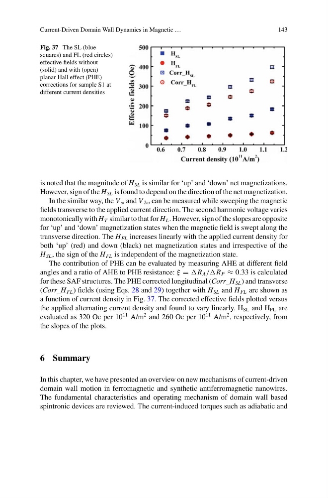
Fig. 37 The SL (blue
squares) and FL (red circles)
effective fields without
(solid) and with (open)
planar Hall effect (PHE)
corrections for sample S1 at
different current densities
is noted that the magnitude of H SL is similar for ‘up’ and ‘down’ net magnetizations.
However, sign of the H SL is found to depend on the direction of the net magnetization.
In the similar way, the V ω and V 2ω can be measured while sweeping the magnetic
fields transverse to the applied current direction. The second harmonic voltage varies
monotonically with H T similar to that for H L . However, sign of the slopes are opposite
for ‘up’ and ‘down’ magnetization states when the magnetic field is swept along the
transverse direction. The H FL increases linearly with the applied current density for
both ‘up’ (red) and down (black) net magnetization states and irrespective of the
H SL , the sign of the H FL is independent of the magnetization state.
The contribution of PHE can be evaluated by measuring AHE at different field
angles and a ratio of AHE to PHE resistance: ξ = R A //R P ≈ 0.33 is calculated
for these SAF structures. The PHE corrected longitudinal (Corr_H SL ) and transverse
(Corr_H FL ) fields (using Eqs. 28 and 29) together with H SL and H FL are shown as
a function of current density in Fig. 37. The corrected effective fields plotted versus
the applied alternating current density and found to vary linearly. H SL and H FL are
evaluated as 320 Oe per 10
11 A/m
2 and 260 Oe per 10
11 A/m
2 , respectively, from
the slopes of the plots.
6 Summary
In this chapter, we have presented an overview on new mechanisms of current-driven
domain wall motion in ferromagnetic and synthetic antiferromagnetic nanowires.
The fundamental characteristics and operating mechanism of domain wall based
spintronic devices are reviewed. The current-induced torques such as adiabatic and
143
Fig. 37 The SL (blue
squares) and FL (red circles)
effective fields without
(solid) and with (open)
planar Hall effect (PHE)
corrections for sample S1 at
different current densities
is noted that the magnitude of H SL is similar for ‘up’ and ‘down’ net magnetizations.
However, sign of the H SL is found to depend on the direction of the net magnetization.
In the similar way, the V ω and V 2ω can be measured while sweeping the magnetic
fields transverse to the applied current direction. The second harmonic voltage varies
monotonically with H T similar to that for H L . However, sign of the slopes are opposite
for ‘up’ and ‘down’ magnetization states when the magnetic field is swept along the
transverse direction. The H FL increases linearly with the applied current density for
both ‘up’ (red) and down (black) net magnetization states and irrespective of the
H SL , the sign of the H FL is independent of the magnetization state.
The contribution of PHE can be evaluated by measuring AHE at different field
angles and a ratio of AHE to PHE resistance: ξ = R A //R P ≈ 0.33 is calculated
for these SAF structures. The PHE corrected longitudinal (Corr_H SL ) and transverse
(Corr_H FL ) fields (using Eqs. 28 and 29) together with H SL and H FL are shown as
a function of current density in Fig. 37. The corrected effective fields plotted versus
the applied alternating current density and found to vary linearly. H SL and H FL are
evaluated as 320 Oe per 10
11 A/m
2 and 260 Oe per 10
11 A/m
2 , respectively, from
the slopes of the plots.
6 Summary
In this chapter, we have presented an overview on new mechanisms of current-driven
domain wall motion in ferromagnetic and synthetic antiferromagnetic nanowires.
The fundamental characteristics and operating mechanism of domain wall based
spintronic devices are reviewed. The current-induced torques such as adiabatic and