

140
S. Krishnia and W. S. Lew
up to few kHz. The harmonic Hall voltage response is recorded while sweeping an
external magnetic field either in the longitudinal or transverse direction to current
flow. Using analytical methods, the effective SL field and field-like (FL) fields are
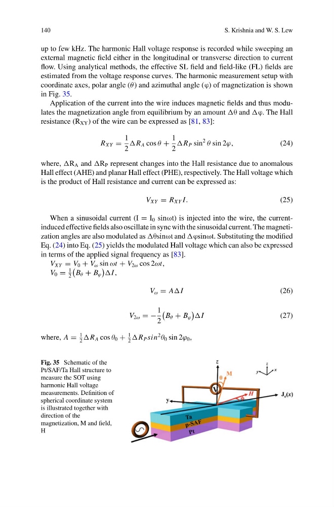
estimated from the voltage response curves. The harmonic measurement setup with
coordinate axes, polar angle (θ ) and azimuthal angle (ϕ) of magnetization is shown
in Fig. 35.
Application of the current into the wire induces magnetic fields and thus modulates the magnetization angle from equilibrium by an amount θ and ϕ. The Hall
resistance (R XY ) of the wire can be expressed as [81, 83]:
R XY =
1
2
R A cos θ +
1
2
R P sin
2
θ sin 2ϕ,
(24)
where, R A and R P represent changes into the Hall resistance due to anomalous
Hall effect (AHE) and planar Hall effect (PHE), respectively. The Hall voltage which
is the product of Hall resistance and current can be expressed as:
V XY = R XY I.
(25)
When a sinusoidal current (I = I 0 sinωt) is injected into the wire, the currentinduced effective fields also oscillate in sync with the sinusoidal current. The magnetization angles are also modulated as θsinωt and ϕsinωt. Substituting the modified
Eq. (24) into Eq. (25) yields the modulated Hall voltage which can also be expressed
in terms of the applied signal frequency as [83].
V XY = V 0 + V ω sin ωt + V 2ω cos 2ωt,
V 0 =
1
2
B θ + B ϕ
I ,
V ω = AI
(26)
V 2ω = −
1
2
B θ + B ϕ
I
(27)
where, A =
1
2
R A cos θ 0 +
1
2
R P sin
2
θ 0 sin 2ϕ 0 ,
Fig. 35 Schematic of the
Pt/SAF/Ta Hall structure to
measure the SOT using
harmonic Hall voltage
measurements. Definition of
spherical coordinate system
is illustrated together with
direction of the
magnetization, M and field,
H
S. Krishnia and W. S. Lew
up to few kHz. The harmonic Hall voltage response is recorded while sweeping an
external magnetic field either in the longitudinal or transverse direction to current
flow. Using analytical methods, the effective SL field and field-like (FL) fields are
estimated from the voltage response curves. The harmonic measurement setup with
coordinate axes, polar angle (θ ) and azimuthal angle (ϕ) of magnetization is shown
in Fig. 35.
Application of the current into the wire induces magnetic fields and thus modulates the magnetization angle from equilibrium by an amount θ and ϕ. The Hall
resistance (R XY ) of the wire can be expressed as [81, 83]:
R XY =
1
2
R A cos θ +
1
2
R P sin
2
θ sin 2ϕ,
(24)
where, R A and R P represent changes into the Hall resistance due to anomalous
Hall effect (AHE) and planar Hall effect (PHE), respectively. The Hall voltage which
is the product of Hall resistance and current can be expressed as:
V XY = R XY I.
(25)
When a sinusoidal current (I = I 0 sinωt) is injected into the wire, the currentinduced effective fields also oscillate in sync with the sinusoidal current. The magnetization angles are also modulated as θsinωt and ϕsinωt. Substituting the modified
Eq. (24) into Eq. (25) yields the modulated Hall voltage which can also be expressed
in terms of the applied signal frequency as [83].
V XY = V 0 + V ω sin ωt + V 2ω cos 2ωt,
V 0 =
1
2
B θ + B ϕ
I ,
V ω = AI
(26)
V 2ω = −
1
2
B θ + B ϕ
I
(27)
where, A =
1
2
R A cos θ 0 +
1
2
R P sin
2
θ 0 sin 2ϕ 0 ,
Fig. 35 Schematic of the
Pt/SAF/Ta Hall structure to
measure the SOT using
harmonic Hall voltage
measurements. Definition of
spherical coordinate system
is illustrated together with
direction of the
magnetization, M and field,
H