

3.4 Solved Problems
75
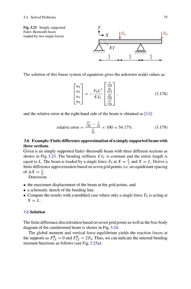
Fig. 3.23 Simply supported
Euler–Bernoulli beam
loaded by two single forces
The solution of this linear system of equations gives the unknown nodal values as:
⎡
⎢
⎢
⎣
u 2
u 3
u 4
u 5
⎤
⎥
⎥
⎦ = −
F 0 L
3
E I Y
⎡
⎢
⎢
⎢
⎣
3
128
41
512
43
256
37
128
⎤
⎥
⎥
⎥
⎦
,
(3.178)
and the relative error at the right-hand side of the beam is obtained as [11]:
relative error =
37
128
−
3
16
3
16
× 100 = 54.17% .
(3.179)
3.6 Example: Finite difference approximation of a simply supported beam with
three sections
Given is an simply supported Euler–Bernoulli beam with three different sections as
shown in Fig. 3.23. The bending stiffness E I Y is constant and the entire length is
equal to L. The beam is loaded by a single force F 0 at X =
L
3
and X = L. Derive a
finite difference approximation based on seven grid points, i.e. an equidistant spacing
of =
L
6
.
Determine
• the maximum displacement of the beam at the grid points, and
• a schematic sketch of the bending line.
• Compare the results with a modified case where only a single force F 0 is acting at
X = L.
3.6 Solution
The finite difference discretization based on seven grid points as well as the free-body
diagram of the cantilevered beam is shown in Fig. 3.24.
The global moment and vertical force equilibrium yields the reaction forces at
the supports as F
R
1Z = 0 and F
R
5Z = 2F 0 . Thus, we can indicate the internal bending
moment functions as follows (see Fig. 3.25a):
75
Fig. 3.23 Simply supported
Euler–Bernoulli beam
loaded by two single forces
The solution of this linear system of equations gives the unknown nodal values as:
⎡
⎢
⎢
⎣
u 2
u 3
u 4
u 5
⎤
⎥
⎥
⎦ = −
F 0 L
3
E I Y
⎡
⎢
⎢
⎢
⎣
3
128
41
512
43
256
37
128
⎤
⎥
⎥
⎥
⎦
,
(3.178)
and the relative error at the right-hand side of the beam is obtained as [11]:
relative error =
37
128
−
3
16
3
16
× 100 = 54.17% .
(3.179)
3.6 Example: Finite difference approximation of a simply supported beam with
three sections
Given is an simply supported Euler–Bernoulli beam with three different sections as
shown in Fig. 3.23. The bending stiffness E I Y is constant and the entire length is
equal to L. The beam is loaded by a single force F 0 at X =
L
3
and X = L. Derive a
finite difference approximation based on seven grid points, i.e. an equidistant spacing
of =
L
6
.
Determine
• the maximum displacement of the beam at the grid points, and
• a schematic sketch of the bending line.
• Compare the results with a modified case where only a single force F 0 is acting at
X = L.
3.6 Solution
The finite difference discretization based on seven grid points as well as the free-body
diagram of the cantilevered beam is shown in Fig. 3.24.
The global moment and vertical force equilibrium yields the reaction forces at
the supports as F
R
1Z = 0 and F
R
5Z = 2F 0 . Thus, we can indicate the internal bending
moment functions as follows (see Fig. 3.25a):